There are lots of frequencies we need to get rid of, but I needed to know what the lowest of them was. That's because the extra low-pass filter in the path from the supply to the output suppresses low frequencies less than high frequencies.
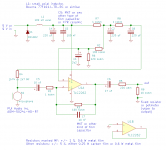
Those sound card microphone inputs usually have an input impedance of only 2.2 kohm. As a result, the output DC blocking capacitor C6 will have to be increased to 47 uF. It's positive and negative sides also may have to be swapped if you go for 5 V supply and no potmeter.
Have you checked if the sound card's microphone input is good enough by itself, without any external preamplifier?
Maybe the best solution is this: increase C6 to 47 uF and always either connect a 10 kohm potmeter or a 10 kohm fixed resistor across the output.
The voltage division between the microphone supply of the sound card and the 10 kohm will reduce the DC voltage a bit, so any reverse voltage across C6 will be far less than the 1.5 V that aluminium electrolytic capacitors can handle. Besides, rumour has it that some sound cards refuse to work unless they see some load on their microphone supply, that's also solved now.
When you use a potmeter, there will be some DC current flowing from the sound card into the wiper. DC wiper current is known to affect the reliability of potmeters, but according to an old Panasonic application note, only when you draw it out of the wiper, not when the current goes into the wiper. Hence, that shouldn't be a problem.
Attachments

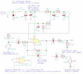
I made a mistake, C3 must be 22 uF because of the reduced R4. Apologies for the inconvenience.
Thanks for the update.. Don't apologies. I haven't even ordered the parts yet and you are more than helpful.
See item 1.4 of the attachment.
I didn't know that and definitely good to know. Thanks again. I will pay attention when soldering it.
Another thought: If it is too complicated to get rid of the interference. Or even impossible. Is it not the easier and a cleaner solution to let the preamp run from it's own power supply? It's still a prototype to prove the concept. If it works then the real engineering has to be done.
Last edited:
No design change, just showing the two options for the output (with and without potmeter) explicitly.
If the crosstalk from the Raspberry Pi remains too high, you can indeed use a separate supply for the time being - a 9 V battery for example 😉 In the bird recording project, hal4287 managed to get his preamplifier working well on the Raspberry Pi supply, but besides the filters, he also needed to look out with how he connected the grounds. I don't know the details of how he connected things in the end.
If the crosstalk from the Raspberry Pi remains too high, you can indeed use a separate supply for the time being - a 9 V battery for example 😉 In the bird recording project, hal4287 managed to get his preamplifier working well on the Raspberry Pi supply, but besides the filters, he also needed to look out with how he connected the grounds. I don't know the details of how he connected things in the end.
Attachments
Last edited:
After some testing i found out the following:
My subwoofer played a sound file (from tone generator 150Hz down to 1Hz)
I recorded this sound on the same device with:
A) The preamp we built here using the WM61A
B) A 13USD Lavalier (Boya BY-M1) microphone without the preamp connected
Whatever the specs or calculations are. At the end we need to pick out a "shape of sound" in the low frequencies from the recording using a spectrogram to train the AI.
So i looked at the Spectrogram of both recordings and both results were almost equally good. Basically the same. Didn't matter how i tweaked the settings.
I still have to do more tests to be really sure about it. But it looks that way.
My conclusion is: All what the preamp does (amplify and low pass filter) we can also do with software later on. Is that correct?
I think you (MarcelvdG) already asked me to do that test which Hal also did a while back. And that test would have maybe proofed the same thing?
Also this thread gives me the idea that i don't actually own a WM61A.
So now i am actually thinking of abandoning the whole PreAmp/filter idea. Which makes everything easier. Maybe the university in Sri Lanka didn't do enough research in that case.
The microphone might make the biggest impact.
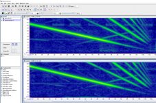
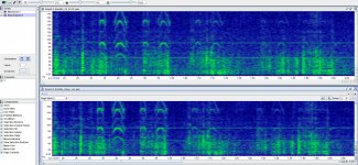
INFO: The sound was not recorded simultaneously. First one and then the other mic attached. The top one is the Lavalier and the bottom spectrogram is from the WM61A preamp.
My subwoofer played a sound file (from tone generator 150Hz down to 1Hz)
I recorded this sound on the same device with:
A) The preamp we built here using the WM61A
B) A 13USD Lavalier (Boya BY-M1) microphone without the preamp connected
Whatever the specs or calculations are. At the end we need to pick out a "shape of sound" in the low frequencies from the recording using a spectrogram to train the AI.
So i looked at the Spectrogram of both recordings and both results were almost equally good. Basically the same. Didn't matter how i tweaked the settings.
I still have to do more tests to be really sure about it. But it looks that way.
My conclusion is: All what the preamp does (amplify and low pass filter) we can also do with software later on. Is that correct?
I think you (MarcelvdG) already asked me to do that test which Hal also did a while back. And that test would have maybe proofed the same thing?
Also this thread gives me the idea that i don't actually own a WM61A.
So now i am actually thinking of abandoning the whole PreAmp/filter idea. Which makes everything easier. Maybe the university in Sri Lanka didn't do enough research in that case.
The microphone might make the biggest impact.
INFO: The sound was not recorded simultaneously. First one and then the other mic attached. The top one is the Lavalier and the bottom spectrogram is from the WM61A preamp.
Attachments
Last edited:
What matters is the equivalent acoustical noise level. The lower the equivalent acoustical noise level, the softer the low-frequency signal can be while still being detectable, and the sooner you can detect elephants coming your way.
If the noise of the sound card is negligible compared to the noise coming out of the microphone anyway, then there is no point building a preamplifier. The microphone then determines the equivalent acoustical noise level of the whole signal chain, and there is nothing a preamplifier can do about it. You can then indeed connect the microphone straight to the sound card and do the amplifying and filtering after the sound card, in software.
If the noise produced by the sound card is much greater than the noise level coming out of the microphone, then a preamplifier will help (assuming the preamplifier itself has low enough noise). It amplifies the microphone's noise until it is well above the sound card's noise, so again the microphone's noise will determine the noise floor of the entire signal chain.
Looked at it in a different (anti-causal) way, the noise of the sound card can be calculated back to a contribution to the equivalent acoustical noise by dividing it by the gain of the preamplifier, if any, and by the sensitivity of the microphone. The higher the gain of the preamplifier, the smaller the contribution of the sound card to the equivalent acoustical noise, but when that contribution is already negligible without any preamplifier, there is no point in making one.
Do your spectrograms still look the same when the subwoofer is set to a very low volume?
I get your point. So if the sound card is "quiet enough" then no need for preamp.
I think many of these soundcards nowadays have these smart noise cancelation chips built in. Could be a bad thing but it seems they do a quite good job.
Here a sound sample from the sound card without microphone attached.
And here with a mic attached which i wrapped in pillows and blankets. But it's just always a bit noisy here. So that doesn't really count as a good test.
Will do the test with the subwoofer tomorrow. And post the results.
... i wrapped in pillows and blankets. But it's just always a bit noisy here. ....
Sound goes *through* fluff pretty good. Wrap your head in a blanket. You still hear almost everything. Fluff does, eventually (many bounces), reduce sound bouncing around *inside* a room.
The classic low-bucks silence chamber is an old-type Pressure Cooker. (I'm not sure these newfangled Instant Pots have enough metal in them.) Drill a small hole (or take out the popper), wire through caulk. Fill inside with fluff and nest the microphone in there. Measure when the trucks are off the roads. Pot in a basement or refrigerator may help a small amount.
I think many of these soundcards nowadays have these smart noise cancelation chips built in. Could be a bad thing but it seems they do a quite good job.
If there is some algorithm built in that suppresses background noise, the question is if it will treat the sounds of distant elephants as background noise. If so, I hope you can switch it off somehow...
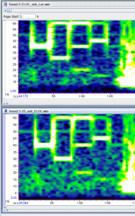
This time i played a sound file with a few seconds of 40Hz 30Hz 20Hz and 15Hz. Played with low volume. But i could have just put the mics further away. Would have done the same effect 🙂
The upper result is from the Lavalier without preamp. Low frequency detection seems to be much cleaner. I did several tests with different devices.
But the "unclean" result can also come from the fake WM61A... so have to do more testing when i have a better mic capsule.
The upper result is from the Lavalier without preamp. Low frequency detection seems to be much cleaner. I did several tests with different devices.
But the "unclean" result can also come from the fake WM61A... so have to do more testing when i have a better mic capsule.
Attachments
Last edited:
Problems with the original circuit:
1. You can not short R5. This will make the op-amp unstable. It should be at least 500 Ohms. A larger R5 resistance allows a smaller C2 but should not be so large that it causes signal loss.
2. C3 is a high pass filter, currently at 72Hz. 25 Hz will be severely attenuated. It does not need to be a bipolar cap. A 22uF electrolytic would be better for a >=7Hz .
3. There is no DC blocking on the output. This may be a problem for what ever is connected to the output and there will be a lot of noise when you adjust VR1. A 10uF electrolytic in series with R5 would block the DC.
a. For the low frequency application, the use of an inverting amp is a poor choice that requires a large C3.
b. Likewise a single supply requires DC blocking caps that a bipolar supply does not. DC blocking caps create a high-pass frequency. You can use two batteries or split a single battery with "ground" set by a divider (R2+R6), ie ground not connected to either battery connection.
c. There is no need for large bipolar caps in such an application.
d. For low frequency applications, choose an op-amp with a low 1/f noise frequency, probably not a FET op-amp. Offset is not an issue for single supply circuits. Rail-rail op-amps are good for battery operation but some are only good for use at 5V. Check the data sheet. Low power is good for battery operation but bad for audio distortion.
You assume that MIC1 is a voltage source, but it is much closer to being a current source. Hence, the cut-off frequency is approximately 1/(2 pi (R4 + R1) C3).
The noise of MIC1 itself increases with 20 dB/decade at low frequencies, so 1/f noise of the op-amp is less of an issue than one would think.
The noise of MIC1 itself increases with 20 dB/decade at low frequencies, so 1/f noise of the op-amp is less of an issue than one would think.
Electret mic impedance
Most electret mics are just a JFET but they are far from constant current sources. Expensive mics are a chip which is essentially an open collector op-amp, ie very low-Z. In any case, the output impedance is not more than 600 Ohms and 2.2uF is too small, but should not be a physically big non-polar cap.
http://www.es.co.th/Schemetic/PDF/KUC.PDF
You should read your own reference a bit better:
Sensitivity
"In the case of electret type it is expressed with a specified resistive load and supply voltage since the output resistance tends towards constant current characteristic."
Output impedance
"In the case of ECMs, the effective output resistance is determined mainly by the value of load resistance. It can be made higher or lower by the value of load resistance with a corresponding change in sensitivity."
In the datasheets I usually see an application circuit with a 2.2 kohm bias resistor, a list of specs that apply to the microphone in its typical application circuit and in that spec list "Impedance: less than 2.2 kohm" or "Output impedance @ 1 kHz: 2.2 kohm". That is, it's not a perfect current source, but it is close.
Access Denied
https://www.puiaudio.com/media/SpecSheet/AOM-5024L-HD-R.pdf
Nonetheless, 2.2 uF is indeed too low for 5 Hz, as was concluded dozens of posts ago.
Here: It's pretty bad. But i haven't tried anything yet.
With the old version i could get it work much better after some better groundings. But at the end still too noisy.
That's how the RPi is powered right now. Don't punish me for that DIY "powerbank" 😀 But that might be one reason for it.
Hey! Very cool project. The way I was able to reduce the noise from the RPi was to add a power management hat (Sleepy Pi) to the RPi. I would plug the power source (12v or 5v battery) into the hat and it would power the RPi on a programmed schedule. I also had long cables runs that would occasionally pick up interference that I reduced using clip-on ferrite cores. The last issue I had was with moisture on the preamp. It didn't take much for it to corrode and start making all kinds of crazy noise before eventually failing. I imagine it's pretty humid there too. I solved this by using a conformal coating (similar to clear finger nail polish) and slathered on a nice thick coat. I also added a waterproof vent to help remove the moisture trapped inside the mic housing. These fixes eliminated my noise issues.
A few other thoughts:
Have you considered the audiomoth device for this project? They are relatively cheap and have been used with LoRa before. I use the preamp Marcel designed for me with it without issue by soldering to a capacitor and using a MOSFET to turn on/off the power to the preamp. Here is a discussion on the topic here:Audiomoth with LoRa | openacousticdevices.
For solar powered projects another thing to consider is heat where the battery and charge controller are. It would be worth it to add appropriate venting to reduce the likelihood that the controller cuts off due to overheating. Hope some of this helps and good luck!
Last edited:
Hi Hal,
thanks a lot for your advise. Definitely good to know.
I didn't know that exits. Very promising but a bit costly. We would like to have machine learning run on our devices so we are still deciding which is the best processor for us. So many options out there 🙂
I would have run into the same "trap". I am sure. So thanks again. In other projects i just sprayed a few layers of clear color on it. Which worked well too.
They already implemented live detection which is not based on ML but algorithms. I think it might be tricky for a algorithm to detect distant rumbles. But worth to look into.
How does your setup turned out in the long run? You have some pictures with runtimes etc?
thanks a lot for your advise. Definitely good to know.
The way I was able to reduce the noise from the RPi was to add a power management hat (Sleepy Pi) to the RPi.
I didn't know that exits. Very promising but a bit costly. We would like to have machine learning run on our devices so we are still deciding which is the best processor for us. So many options out there 🙂
I solved this by using a conformal coating (similar to clear finger nail polish) and slathered on a nice thick coat
I would have run into the same "trap". I am sure. So thanks again. In other projects i just sprayed a few layers of clear color on it. Which worked well too.
I have. And after you told me they also used LoRa with it i took a closer look. That seems doable. Would be the perfect platform. Unfortunately our AI guy told me the chip RAM is too small to run any kind of AI on it. But let's see. Maybe we can modify it for our needs.Have you considered the audiomoth device for this project?
They already implemented live detection which is not based on ML but algorithms. I think it might be tricky for a algorithm to detect distant rumbles. But worth to look into.
How does your setup turned out in the long run? You have some pictures with runtimes etc?
- Home
- Source & Line
- Analog Line Level
- Preamp for Mic for makes high pitched noise