When R4 is reduced to 4.7 kohm for 5 V supply, C3 has to be increased to 10 uF, which starts to get expensive in MKT. Panasonic has some cheap bipolar electrolytics, but those may not be available everywhere. The most practical solution would probably be using an ordinary 10 uF electrolytic capacitor and measuring with what polarity it has to be connected in the circuit.
Thanks again for still improving it. I would love to have already implemented all your suggestions. But i am still waiting for the parts 🙁
But meanwhile. There are still some questions in my head:
Can i use MKP instead of MKT?
But meanwhile. There are still some questions in my head:
Can i use MKP instead of MKT?
So if i use 38 pF then i will basically have a good and cheap all purpose DIY -mic?MarcelvdG said:Connect a 10 nF MKT or NP0 ceramic multilayer capacitor in parallel with R3 if low-pass filtering is desired, otherwise 39 pF NP0 ceramic (or 100 pF if a roll-off at 16 kHz is OK).
You can definitely use MKP. The reason why I suggested MKT is that MKT is usually cheaper and smaller than MKP and is still good enough for your application. That is, I can't imagine that the minor technical imperfections of MKT capacitors will hinder the detection of elephants in any way.
39 pF for the capacitor in parallel with R3 would indeed be a good value for general applications.
About the changes I suggested for 5 V supply, so R4 reduced to 4.7 kohm or 4.75 kohm and C3 changed to 10 uF electrolytic, one can actually calculate that the positive terminal of the electrolytic capacitor then has to be on the microphone's side. Both the WM-61A and the AOM-5024L-HD-R draw at most 0.5 mA, so the drop across the reduced R4 will be at most 2.375 V while the op-amp's input is biased at half the supply voltage. So no need to measure the polarity, just connect the positive side to the microphone.
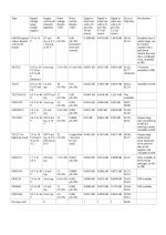
That's a low-offset version of the TLC272. As low offset isn't needed and only one channel is used, you may then use the cheaper TLC271 instead: 25 nV/sqrt(Hz) at 1 kHz in high bias mode, $0.96 ... $1.27 at Digi-Key, 0.675 mA typical at 5 V and 0.95 mA typical at 10 V in high bias mode.
I didn't look at the TLC27x family because the TLC2262 is advertised as a performance upgrade for the TLC27M2. I should have checked the price difference, though.
I didn't look at the TLC27x family because the TLC2262 is advertised as a performance upgrade for the TLC27M2. I should have checked the price difference, though.
Attached is an updated op-amp list, the additions are the TLC271 and the estimated loss of signal-to-noise ratio due to op-amp noise when the microphone's bias resistor is 4.7 kohm.
One thing that is likely to go wrong if you should combine the amplifier's supply with the single-board computer's supply is crosstalk from the computer and the power supply to the microphone preamplifier. The most likely path is via the microphone's bias resistor R4. In Hal's bird recording thread I just advised him to put some brute-force filters in the circuit as a precaution, but then again, his budget wasn't as low as yours and the frequencies he was interested in were easier to filter. If you want to keep everything as cheap as possible, you first have to check if there is a problem at all and how bad it is.
One thing that is likely to go wrong if you should combine the amplifier's supply with the single-board computer's supply is crosstalk from the computer and the power supply to the microphone preamplifier. The most likely path is via the microphone's bias resistor R4. In Hal's bird recording thread I just advised him to put some brute-force filters in the circuit as a precaution, but then again, his budget wasn't as low as yours and the frequencies he was interested in were easier to filter. If you want to keep everything as cheap as possible, you first have to check if there is a problem at all and how bad it is.
Attachments
Last edited:
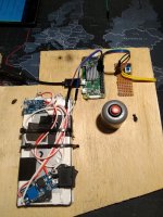
Finally the parts have arrived and i build a prototype with all the modifications (suggested from super helpful MarcelvdG) on a breadboard. Unfortunately there is no sound output. Even i tab on the mic... nothing.
But maybe i made the wrong circuit. To clear things up:
ver_01 is the circuit with the hissing sound.
ver_02 after i made the modifications i got from this forum (works pretty good already. Sound compare: with LM358 and TLC2262 )
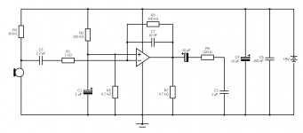
ver_03 is how i interpret this post
Is ver_03 correct? Or did i misunderstood something?
What i have measured with a 7V supply voltage:
Mic gets around 3,8V
GND - pin 2 OPAMP: -0,87V
GND - pin 3 OPAMP: - 0,55V
GND - pin 8 OPAMP: 7V
GND - C6 (negative side): -1,1mV
GND - C6 (positive side): -39,3mV
C7: Does MKM work instead of MKT?
I used The LM3598 and the TLC2262 with same results.
If you think this info does not sound logical ad all. I will check all again Which i already did three times though 🙂
Trying to get this running first before i implement the 5V modifications.
Thanks again for all the support.
But maybe i made the wrong circuit. To clear things up:
ver_01 is the circuit with the hissing sound.
ver_02 after i made the modifications i got from this forum (works pretty good already. Sound compare: with LM358 and TLC2262 )
ver_03 is how i interpret this post
Is ver_03 correct? Or did i misunderstood something?
What i have measured with a 7V supply voltage:
Mic gets around 3,8V
GND - pin 2 OPAMP: -0,87V
GND - pin 3 OPAMP: - 0,55V
GND - pin 8 OPAMP: 7V
GND - C6 (negative side): -1,1mV
GND - C6 (positive side): -39,3mV
C7: Does MKM work instead of MKT?
I used The LM3598 and the TLC2262 with same results.
If you think this info does not sound logical ad all. I will check all again Which i already did three times though 🙂
Trying to get this running first before i implement the 5V modifications.
Thanks again for all the support.
Attachments

Correction of the ver_02 circuit in my last post:
C2 is removed
But that is without low pass filter i guess right?
C2 is removed
This one work very well, i use it for my mixer....
But that is without low pass filter i guess right?
Finally the parts have arrived and i build a prototype with all the modifications (suggested from super helpful MarcelvdG) on a breadboard. Unfortunately there is no sound output. Even i tab on the mic... nothing.
But maybe i made the wrong circuit. To clear things up:
ver_01 is the circuit with the hissing sound.
ver_02 after i made the modifications i got from this forum (works pretty good already. Sound compare: with LM358 and TLC2262 )
ver_03 is how i interpret this post
Is ver_03 correct? Or did i misunderstood something?
What i have measured with a 7V supply voltage:
Mic gets around 3,8V
GND - pin 2 OPAMP: -0,87V
GND - pin 3 OPAMP: - 0,55V
GND - pin 8 OPAMP: 7V
GND - C6 (negative side): -1,1mV
GND - C6 (positive side): -39,3mV
C7: Does MKM work instead of MKT?
I used The LM3598 and the TLC2262 with same results.
If you think this info does not sound logical ad all. I will check all again Which i already did three times though 🙂
Trying to get this running first before i implement the 5V modifications.
Thanks again for all the support.
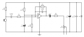
In the right circuit, R6 should be 100 kohm, C2 shouldn't be there and R7 shouldn't be there when you use the TLC2262 (only meant for the LM358). C3 should be 4.7 uF.
I had never heard of them before, but MKM capacitors should work fine.
Last edited:
In the right circuit, R6 should be 100 kohm, C2 shouldn't be there and R7 shouldn't be there when you use the TLC2262 (only meant for the LM358). C3 should be 4.7 uF.
I had never heard of them before, but MKM capacitors should work fine.
Ohh. I don't know how that happened. But it seems i accidentally uploaded a wrong version of the ver03 circuit. So this here is correct picture of the circuit which didn't give me any sound output. So the voltage measurements from my last post apply to this new uploaded circuit.
Sorry for wasting your time with my mistake.
Attachments
First thing to check would be the positive input, pin 3. It's supposed to be biased at about half the supply voltage. Pins 2 and 1 then basically copy pin 3's DC voltage.
First thing to check would be the positive input, pin 3. It's supposed to be biased at about half the supply voltage. Pins 2 and 1 then basically copy pin 3's DC voltage.
Yap. You are the man. That made me find the problem. In computer terms i always used to say: The problem sits mostly between the chair and the monitor. Of course this case was no different. I haven't connected PIN 1 at all.
So now i get some output but it is very very quiet: Blowing into the mic from 2cm distance
Another hint?
Of course always good to compare with another solution. Any idea how to get a low pass filter in there?This one work very well, i use it for my mixer....
The voltage at pin 3 should be independent of whether you connected pin 1, so I don't understand how connecting pin 1 can fix the wrong voltage at pin 3.
Do you get the correct bias voltages now, about half supply at pins 1, 2 and 3 and supply minus 2 V ... 5 V across the microphone?
Do you get the correct bias voltages now, about half supply at pins 1, 2 and 3 and supply minus 2 V ... 5 V across the microphone?
I don't know what it was but suddenly it works now. I didn't change anything. Maybe my audio cable has a short or so. Or some other loose connection.
Here a sound example which is a bit clipping because too close to the mic.
Very cool. Thanks again for your patience and help @MarcelvdG and of course everybody else who gave input here.
In the next months i will be going to a national park here on Sumatra and do some elephant recordings for a while.
BTW. As you already mentioned earlier. There is indeed strong disturbance coming from the raspberry when i use the same power source. And maybe the best solution is to separate the power supplies. But of course if you have a nice solution. I am all yours 🙂
If it comes to the price tag. The project leader told me we can spend a bit more if it works at the end 🙂
Can you make and post a recording of just the interference from the Raspberry Pi?
Here: It's pretty bad. But i haven't tried anything yet.
With the old version i could get it work much better after some better groundings. But at the end still too noisy.
That's how the RPi is powered right now. Don't punish me for that DIY "powerbank" 😀 But that might be one reason for it.
Attachments
Last edited:
I think you need some brute-force low-pass filters, similar to what we used in the bird recording thread. I'll draw a schematic and post it. At least I know now that I didn't waste Hal's money by including them in his preamplifier...
In the GoldWave spectrum plot, the interference from the Raspberry Pi looks like 23 Hz and its harmonics plus a big peak around 1003 Hz. See the attachment, the horizontal axes are in Hz and the vertical ones in dB with respect to some unknown reference. The bottom graph is a zoom of the first 200 Hz.
In the GoldWave spectrum plot, the interference from the Raspberry Pi looks like 23 Hz and its harmonics plus a big peak around 1003 Hz. See the attachment, the horizontal axes are in Hz and the vertical ones in dB with respect to some unknown reference. The bottom graph is a zoom of the first 200 Hz.
Attachments

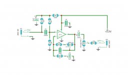
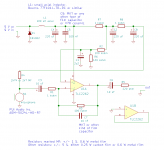
This is the best I could come up with. Is the sound card's input a line input or actually a microphone input with a DC bias voltage on it?
Changes:
-Extra filter components added: L1, R7, C2, R8, C8. D1 is a diode to protect against reversed polarities and a freewheeling diode for L1.
-Values of C1, C4, R4 and R6 changed.
-R2 connected after the first section of the new filter.
-I didn't draw the potmeter, but just add it if needed.
Changes:
-Extra filter components added: L1, R7, C2, R8, C8. D1 is a diode to protect against reversed polarities and a freewheeling diode for L1.
-Values of C1, C4, R4 and R6 changed.
-R2 connected after the first section of the new filter.
-I didn't draw the potmeter, but just add it if needed.
Attachments
Oh i understand. So it's basically "just one" frequency we need to get rid of and the rest disappears with it.
For now we are using a USB sound card which has an actual MIC input. It measures 3,2V.
As usual i will have to wait for parts to arrive. And i will report back when i got stuck somewhere or i actual do not make a mistake this time and it will all work 🙂
Thanks again for all your effort. I really appreciate it.
- Home
- Source & Line
- Analog Line Level
- Preamp for Mic for makes high pitched noise