John,
There are two types of users. Those that primarily use their remote control and those that rely on the encoder for volume. While I try to leave my preamp on all the time, on those rare occasions where I need to turn it off, I find using the encoder to be incredibly frustrating because it will skip a 10-cycle quite often when moved rapidly. As you don't save the current settings before power-off, everything "zeroes out". From zero, it is difficult to move the encoder slowly when the default listening volume level is 150 or so. This is not an issue with the remote.
In my office, where I am using one Nano version, I was only a few feet from the encoder, so it was easier to just try to use it. I found the experience to be so frustrating that I moved a remote into the office. If I weren't using a remote, I would consider the system to be unsatisfactory. This is not something that I think commercial customers would be willing to live with. If you would just save the volume settings between power-offs, you could probably get by with it, but there will still be complaints. Regardless of how good it sounds; I think you still must deal with it.
Regards,
Roy
Yes, The Nano only has 2 interrupt pins but that can be resolved.
My use (and therefore my code) has two encoders that are the 'push' type, ie. as well as rotating you can press them in for a momentary action. Pushing the volume encoder toggles 'mute'; pushing the input select encoder enters/exits standby. Supporting those leads to the need for 5 interrupt pins. The Atmega328 on the Nano also supports "Pin Change" interrupts where an interrupt occurs when any pin on a PORT changes. Using those is not as difficult as it might first look. So there's no need to look for a different Arduino; I'll quite happily provide you with suitable code.
My use (and therefore my code) has two encoders that are the 'push' type, ie. as well as rotating you can press them in for a momentary action. Pushing the volume encoder toggles 'mute'; pushing the input select encoder enters/exits standby. Supporting those leads to the need for 5 interrupt pins. The Atmega328 on the Nano also supports "Pin Change" interrupts where an interrupt occurs when any pin on a PORT changes. Using those is not as difficult as it might first look. So there's no need to look for a different Arduino; I'll quite happily provide you with suitable code.
In my version of a volume /remote/encoder/source select controller using a Nano, I've made use of a piece of native AVR code within my Arduino C++ coding to enable an Analog Compare Interrupt which I use with an Interrupt service routine ( ISR(ANALOG_COMP_vect) ) which saves all the settings for use on restart. I can PM you with info if it's of interest.It will take a different Arduino with at least 3 interrupts. But I will look into it.
My understanding is that "Analog Compare" is limited to which pins may be used, whereas "Pin Change" will work on any digital I/O port.
You're absolutely right and will only work with any of the Analog I/O pins. Using the "Analogue Compare" function enabled me to use a scaled down (via a resistor divider) sample from Vin and sense a significant drop in the unregulated input voltage. The resultant "Power-down interrupt" can then save the volume and source settings before the supply voltage gets too low and the Arduino goes into shutdown.My understanding is that "Analog Compare" is limited to which pins may be used, whereas "Pin Change" will work on any digital I/O port.
As a means to save and reinstate setting, it works well . If it's of interest (not necessarily for this particular circuit layout), here's a link - https://github.com/GeoffWebster/PreAmpController
Last edited:
Yes, I can see the strength of Analog Compare for spotting voltage drop. My suggestion of Pin Change is for use with the encoders, which are essentially on/off so well suited to Pin Change.
I didn't implement "save settings on power down"; I implemented a "standby" type of power on/off from the remote (or a push button) and saved settings on entering standby. If there is a power cycle, the settings return to the last time it entered standby.
I didn't implement "save settings on power down"; I implemented a "standby" type of power on/off from the remote (or a push button) and saved settings on entering standby. If there is a power cycle, the settings return to the last time it entered standby.
There's nothing to stop you doing both types of interrupt, one for the analog sensing the voltage drop, the other for the pin change of the encoder or remote decoderYes, I can see the strength of Analog Compare for spotting voltage drop. My suggestion of Pin Change is for use with the encoders, which are essentially on/off so well suited to Pin Change.
I didn't implement "save settings on power down"; I implemented a "standby" type of power on/off from the remote (or a push button) and saved settings on entering standby. If there is a power cycle, the settings return to the last time it entered standby.
So for my Current circuit layout, since the Nano only had two interrupts I used one for the IR remote but the rotary encoder is attached to two analog pins, A0 and A1, which are currently being used as digital inputs but the Analog Pin Change sounds interesting. I am a programmer but new to Arduino and other embedded Microprocessor. Please send me any info/code on this and I will see what can be done. While the IR remote is smooth the encoder is not a smooth as it should be and if it can be fixed in code rather than a processor board change than I am very interested.
BTW, I had the push button on the switch setup to do a fast volume up since I have a mute button already, but with the latest change the momentary switch in the encoder is not used.
Thanks,
John
BTW, I had the push button on the switch setup to do a fast volume up since I have a mute button already, but with the latest change the momentary switch in the encoder is not used.
Thanks,
John
For reading a shaft encoder, do you even need to go for interrupts? When IThere's nothing to stop you doing both types of interrupt, one for the analog sensing the voltage drop, the other for the pin change of the encoder or remote decoder
did my implementation of shaft encoders with Arduino I used the example
code on the Arduino site and it worked fine. It isn't interrupt driven just
polled and even at that I had to slow down the polling rate to 500 Hz from
1KHz to deal with contact bounce from the mechanical (not optical) shaft
encoder. The softeware runs on a 1 mllisecond timer for certain operations
like auto fade rate, shaft encoders, display update and such. To save settings
you could have a small power off delay so that when a power down is selected,
the power would remain up on the Arduino so that all run parameters could be
saved. Using EEPROM.update(xxx) it checks to see if the value is different and
only writes if different so you don't 'use up' the limited write cycles into the EEPROM.
G²

My implementation (see my recent reply) doesn't use interrupts for rotary encoder or remote either. The only interrupt I'm currently using is for the time critical function of power-down sensing / saving settings.For reading a shaft encoder, do you even need to go for interrupts? When I
did my implementation of shaft encoders with Arduino I used the example
code on the Arduino site and it worked fine. It isn't interrupt driven just
polled and even at that I had to slow down the polling rate to 500 Hz from
1KHz to deal with contact bounce from the mechanical (not optical) shaft
encoder. The softeware runs on a 1 mllisecond timer for certain operations
like auto fade rate, shaft encoders, display update and such. To save settings
you could have a small power off delay so that when a power down is selected,
the power would remain up on the Arduino so that all run parameters could be
saved. Using EEPROM.update(xxx) it checks to see if the value is different and
only writes if different so you don't 'use up' the limited write cycles into the EEPROM.
G²
Debouncing of the rotary encoder is dealt with by use of a state machine within the rotary library (based on Ben Buxton's excellent library). This library can be used as part of an interrupt routine or simply by polling it within the Arduino loop() routine.
The RC5 routine (remote controller) I use is the superb Guy Carpenter library which is another state machine driven library. This can also be interrupt triggered or polled.
Just because we're using Arduino code doesn't prevent including native AVR stuff or your own C++ routine to enhance it. That's what the Pin Change Interrupt routine and others are doing.
Last edited:
Your comments are, of course, quite true. There's no need to use interrupts for the encoder, you can poll within loop(). But in my opinion, it's the best approach particularly when polling more than one button/encoder/switch; the code in loop() is simpler as there is just the need for checking a few booleans.
The ideas for saving settings to EEPROM are also valid, as are other suggestions for future developments, but first things first. John, in a couple of posts ago, is first trying to improve the response to the encoder (the remote seems OK). He also invites information or examples of code so I shall respond to that in due course.
Geoff
He also invites information or examples of code so I shall respond to that in due course...Your comments are, of course, quite true. There's no need to use interrupts for the encoder, you can poll within loop(). But in my opinion, it's the best approach particularly when polling more than one button/encoder/switch....
Here's the library I'm using for the encoder - https://github.com/CarlosSiles67/Rotary
It's quite happy using interrupts and runs pretty smoothly. It also handles the push switch built into the shaft of the encoder
Geoff
The encoder code I am using is from the Arduino.cc site library. It works best using interrupts but is only ok without. Spin the encoder too fast and the code can’t determine the direction so the volume could go up or down when trying to turn up. Polling didn’t even work as well as the current library code. But I am definitely interested in the pin change idea. Any sample code?
I tried the Ben Buxton library this morning wondering if it would be better thanThe encoder code I am using is from the Arduino.cc site library. It works best using interrupts but is only ok without. Spin the encoder too fast and the code can’t determine the direction so the volume could go up or down when trying to turn up. Polling didn’t even work as well as the current library code. But I am definitely interested in the pin change idea. Any sample codeerI tried the Ben Buxton library this morning wondew
the non-library code I started using in Sept 2017 originally from HT electronics.
The HT code misses ticks (one tick of rotation) when turned very rapidly and will
occasionally count the opposite direction, rarely more than 1 count. I got the
same behavior with the Buxton code. When I added the encoder to my code 5
years back I was already using pins 3,4 & 5 for other functions so when HT's code
used A0,A1 & A2 I just left it that way. I don't think swapping pins 3, 4, & 5 with
A0,A1 & A2 makes a difference. I would prefer NOT to change the hardware and
software for no improvement.
G²
Attachments
Thanks, I will read through the code. Most I have read were similar to what I wrote on the third iteration. I generally can read and learn from most code but after so long I had to settle on something until I had time dig into it more. I want it to be flawless, like you would find in a professional design. And once I get a little more time I will dig into it again. Everything else works great and sounds excellent, just the rotary encoder needs to work better. Once I get it I will post the new code. Worse comes to worse the Nano will be replaced by another in the Arduino line, but I would rather not change hardware unless it is really necessary.
You added a comment querying the detection of transitions - is it just the fall of pin A or possibly ALL transitions. The expression in the 'if' will be true if 'encoder_A_prev' is 1 AND '!encoder_A' is also 1 (NOT 'encoder_A' being 1 means 'encoder_A' is 0). Therefore it is only true if 'encoder_A' was previously 1 and it is now 0. The comment from HT-Electronics is correct.the non-library code ... originally from HT electronics.
As I noted in my attachment to post #439, at the moment pin A falls (from HIGN to LOW) the value of pin B indicates whether the rotation is clockwise or counter-clockwise and this code adopts that (simple) approach - for volume control there is no need for full quadrature. You should note that here I wrote "at the moment pin A falls". Consider the case of the encoder turning clockwise. At the moment pin A falls, pin B is high; the next thing to happen (very soon after) is pin B falls. If there is a delay between pin A falling and the code getting the value of pin B, it's just possible that the delay is long enough for pin B to fall during that delay period so you get the wrong value of pin B. In that case the code will think the rotation is the other way.
Considering the HT-Electronics code, let's imagine that pin A has been read and it has not yet fallen; also imagine that pin A falls a few microseconds after this read. By virtue of the code, it will be almost a millisecond before pin A is read again; to this we need to add the execution time of the digitalReads (it might be longer depending on what other code is executed in the loop). So here is a situation where it is over a millisecond between pin A falling and the code reading the value of pin B and noticing that pin A has fallen. If the encoder is rotating very quickly then pin B might have fallen during that delay.
Where you write "when turned very rapidly and will occasionally count the opposite direction, rarely more than 1 count", could this be the cause?
If only there were a way to get code executed very rapidly after the state of pin A changes. If only ...
Well, I can think of a way ... but several people tell me that there's no need to use interrupts.
Yes, using interrupts can be daunting but if you want robustness, as John puts it " like you would find in a professional design" it might be worth going that extra mile.
Geoff
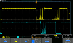
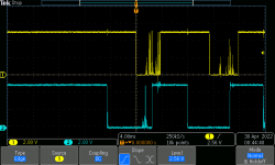
I got out the scope this morning and took a look at the 2 signals into the Arduino andYou added a comment querying the detection of transitions - is it just the fall of pin A or possibly ALL transitions. The expression in the 'if' will be true if 'encoder_A_prev' is 1 AND '!encoder_A' is also 1 (NOT 'encoder_A' being 1 means 'encoder_A' is 0). Therefore it is only true if 'encoder_A' was previously 1 and it is now 0. The comment from HT-Electronics is correct.
As I noted in my attachment to post #439, at the moment pin A falls (from HIGN to LOW) the value of pin B indicates whether the rotation is clockwise or counter-clockwise and this code adopts that (simple) approach - for volume control there is no need for full quadrature. You should note that here I wrote "at the moment pin A falls". Consider the case of the encoder turning clockwise. At the moment pin A falls, pin B is high; the next thing to happen (very soon after) is pin B falls. If there is a delay between pin A falling and the code getting the value of pin B, it's just possible that the delay is long enough for pin B to fall during that delay period so you get the wrong value of pin B. In that case the code will think the rotation is the other way.
Considering the HT-Electronics code, let's imagine that pin A has been read and it has not yet fallen; also imagine that pin A falls a few microseconds after this read. By virtue of the code, it will be almost a millisecond before pin A is read again; to this we need to add the execution time of the digitalReads (it might be longer depending on what other code is executed in the loop). So here is a situation where it is over a millisecond between pin A falling and the code reading the value of pin B and noticing that pin A has fallen. If the encoder is rotating very quickly then pin B might have fallen during that delay.
Where you write "when turned very rapidly and will occasionally count the opposite direction, rarely more than 1 count", could this be the cause?
If only there were a way to get code executed very rapidly after the state of pin A changes. If only ...
Well, I can think of a way ... but several people tell me that there's no need to use interrupts.
Yes, using interrupts can be daunting but if you want robustness, as John puts it " like you would find in a professional design" it might be worth going that extra mile.
Geoff
while not pretty, they are typical of mechanical encoders. These cheapy encoders are
1 cycle per tick, and 20 cycles per revolution. I define a tick as rotating 1 position either
way to the next tick. That noise is dirt in the contacts. If you attempt to read that via
interrupts the processor will do a lot of work chasing the noise. The Grayhill encoders
I used long ago on another project were true Gray code encoders where there was 1
CHANGE per tick of EITHER the A or B readout so for a 16 position encoder, there were
4 cycles per revolution. To decode those you need to detect ALL transitions. The Grayhill
were optical meaning an LED and photo transistor so there was no noise on either phase.
If you're counting where it is imperative there be no errors, you must use optical units.
G²
Attachments
Last edited:
I agree that the encoders are noisy, as are push buttons and other switches. It is necessary to 'debounce' them. In hardware, given a pull-up resistor, the minimum is a capacitor to ground - empirically this works well but more sophistication is possible. Looking at John's hardware designs it is clear that John understands the need for debouncing.
Hi Stratus46,
For those scope readings were there caps across the pins to ground. It is recommended to use a .01uf cap on each pin to absorb the noise, and I find this to work.
Finding good rotary encoders that don't have shaft wobble and are not expensive is the hard part. The Optical units are nice but too expensive, though I might take another look at them.
___________________
For the code, an interrupt is the best way to get the instant of the pin falling, polling can take too long and can miss a state as it is doing now, if at the interrupt you then immediately read the other pin you can determine the direction. I will learn more of the Pin Change Interrupt, which works with the current PCB layout, and also look at using the other interrupt pin of the Nano for one pin of the encoder, which requires a couple cuts and jumps, then in an ISR immediately read the other pin then return to the main loop to determine up or down.
Anyways, more stuff to try and investigating Geoff's code. Just need more time from my regular job to play.
- Home
- Source & Line
- Analog Line Level
- Preamp Control - Volume, input, mute, remote