John,
We still have R5 sitting empty on the remote PCB, that is included in the schematic without a value but not listed in the BOM?
We still have R5 sitting empty on the remote PCB, that is included in the schematic without a value but not listed in the BOM?
John,
I am trying to make sense of your display schematic that you updated with the new display PCB.
I believe that:
1. U8 on the schematic is U2 on the PCB
2. D6 on the schematic is D5 on the PCB
3. R39 on the schematic is R9 on the PCB
4. D5 on the schematic is D6 on the PCB
5. R9 on the schematic is R10 on the PCB
Please let me know if this is correct>
Regards,
Roy
ok, R5 on the Remote is a pull down and should be 100k like R1-4, another new part for the new encoder. I have updated the BOM.
D5 on both the schematic and Board is the transmission valid LED from the encoder and I chose Blue. D6 on both the schematic and Board is the Mute LED and I chose Red that that one.
U2 on both the schematic and Board is the Decoder chip. There is no U8 on the display board.
R39 on both the schematic and Board is a display segment current limiter.
R9 on both the schematic and Board is the valid transmission LED current limiter.
R10 on both the schematic and Board is the mute LED current limiter.
Make sure you are using the latest Schematic, I am looking at the one in this site.
Attached is the update BOM.
Attachments
John,
I must have had an older version of the schematic, they are all corrected in the new one. It might be a good idea to have the latest copy of all pictures, documentation and gerbers it the end of the first post. I have seen that approach work very well in other project threads, particularly when they start to get complicated.
Regards,
Roy
I have the post # for the current post in the first post but I will try adding the latest of each file to the first post. Thanks for the idea.
Pictures of the New PCBs
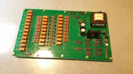
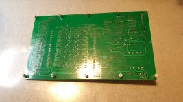
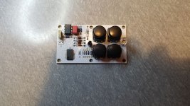
I have mostly finished stuffing the three PCBs for the project. Main and display are complete; however, I had to kluge R11 (150R) on the display board to account for its small form factor. The remote control PCB is still missing a few small form factor resisters.
I have started testing and have found that the switching and mute are working as expected. I am still having problems volume as the volume LEDs do not update, the volume changes are hard to precisely control and the resistance measurements are erratic. I will wait to compare my results with John's before I go much farther.
Attachments


if you want to pick a specific volume number easier you can change the resistors on the 555 timer to slow the rate of change to slightly slower.
Are the Volume 7 segment LED lighting up? If so check the input to the volume counter and see if it is incrementing/decrementing. An oscilloscope makes things easier to see but a volt meter will show a low level to high level change as you step. Let me know what you find.
Are the Volume 7 segment LED lighting up? If so check the input to the volume counter and see if it is incrementing/decrementing. An oscilloscope makes things easier to see but a volt meter will show a low level to high level change as you step. Let me know what you find.
John,.
All the LEDs are lighting up and the mute light works. The input LEDs change properly but the three volume LEDs stay fixed at the number they started with, usually 555.
Regards,
Roy
All the LEDs are lighting up and the mute light works. The input LEDs change properly but the three volume LEDs stay fixed at the number they started with, usually 555.
Regards,
Roy
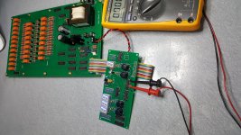
My mistake, I was on U3.3 (Mute), when I tried U3.1 the voltage was varying all over the place and I didn't see a definite pulse on the volt meter. The relays were responding though. Also, it seems like the relays chatter for about 4 to 5 seconds on power up, is this normal?
The LEDs should be starting at 000, if not the reset controller chip is not resetting something. Double check the part number on the reset controller, it should be MCP101-475DI/TO if they sent you the HI/TO it will not reset in this circuit.
It is the right reset controller. Do you think that at least some of the extended relay chatter at startup may be happening after reset?
No relays should be active at startup, not until a button is pushed. Something in the volume section is not right, check all the chips for correct type and orientation, and solder splashes.
I will work on the troubleshooting guide sooner rather than later.
I will work on the troubleshooting guide sooner rather than later.
All chips are in the proper orientation and there are no solder splashes. All chips match the BOM with the exception of U17. It is a SN74LS145N not a SN74LS145NE4.
U17 p/n isn't a problem, besides the input section works.
Let me see if I can get some time today to write a troubleshooting guide, at least on the volume section to start.
Let me see if I can get some time today to write a troubleshooting guide, at least on the volume section to start.
Thanks John, that's what I thought when I traced it out on the circuit diagram. Troubleshooting the main board may be a bit of a problem. The circuit diagram for the main board's resolution is too low to be able to read the pin numbers conclusively. You can kind of guess from a chip's data sheet, but there is still some ambiguity.
main board in large scan
Even printed in 11x17 I have trouble seeing the pin numbers, but if you look at the data sheet and the pin function on the schematic you can figure the pin number.
You said you are getting some relay chatter at startup but no relays should be active. Try unplugging the ribbon cable from both boards which will isolate the input buttons from the main board, best would be then to tie pin 17 to 18 and 19 to 20 on the main board ribbon cable connector so the input pins are grounded to the AND gate, U2, not floating. This will tell you if the problem is on the main board or the display board, or possibly the ribbon cable. If your chatter is gone when you power up then it is either ribbon or display board.
Let me know what happens
Some very faint clicks, one may be two, and that's it. Tried it four or five times and always heard at least one faint click. This is nothing like the four or five seconds of constant chatter before it settles down. The display board comes up on input "7" and volume "555".
Without the ribbon cable connected there will not be a reset pulse to the display board so they will come up in any state. Interesting that the volume display shows the same as when there is a problem. Still shouldn't be any relay clicks just at power up, would be interesting to know which one(s) are clicking. So nothing pointing to the problem yet so start by testing the display board button function. With power to the boards you can push one button at a time and read the voltage change on the ribbon cable connector pins from the front side of the board. For the volume button look for a high, 3.5 to 4.5 volts, on the inputs to the inverter U1, pins 1 and 3, up/down respectively, and pin 5 for mute and pin 9 for input sel. Then the outputs of the inverter pins 2, 4, 6, and 8 should be low, .3 to .8 volts. Pushing a button and holding should have the high going low and vice versa. Follow it to the OR gate U3 inputs, pins 2, 5, 9, and 12, and then the OR gate outputs, pins 3, 6, 8, and 11, they should follow the output of the inverter.
Try plugging in the ribbon cable on just the main board and see what happens. I have built 5 proto boards and 20 revision 2 main boards and not had any problems except with a bad cable, the Insulation Displacement Connections, IDC, can miss occasional if you are not really careful.
Try plugging in the ribbon cable on just the main board and see what happens. I have built 5 proto boards and 20 revision 2 main boards and not had any problems except with a bad cable, the Insulation Displacement Connections, IDC, can miss occasional if you are not really careful.
- Home
- Source & Line
- Analog Line Level
- Preamp Control - Volume, input, mute, remote