Calvin CFP2
Hi to all,
did anyone actually build the CFP2 Version of the Buffer?
When I ordered boards for another project I couldn't resist and added some of my CFP2 boards (nix Watje 😉). Later I found an error that could be fixed with some point to point wiring on the board. However I could not get it working 😕 Don't have the time to dig a little deeper at the moment however just wanted to know if the design works in hardware as it does in simulation.
regards, Daniel
Following. I'm looking for a preamp buffer to follow Muses volume control. Does anyone know if parts availability is still an issue? Thx
Hi,
curryman, I´m sorry that You´re CFP² doesnt work at once.
Seems that we have to take a closer look at how You implemented it.
jauu
Calvin
curryman, I´m sorry that You´re CFP² doesnt work at once.
Seems that we have to take a closer look at how You implemented it.
jauu
Calvin
Success
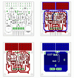
I just ordered some PCBs for other projects and couldn't resist to add some revised CFP2 boards 😀
Today I did a first test and it looks quite promising. Right from the first start the board works 🙂
I used matched BF862 instead of LSK389 (since the latter is quite expensive, board will take both), the rest is identical to schematic from post #190. The next days I'll do some more in depth tests and some listening.
The actual layout is a bit quick and dirty to be honest and it might be possible to further improve it but actually it seems to work quite well 😉
Best regards, Daniel
PS: I also did some boards for the "original" Calvin buffer (all SMD) and a symmetrical version 🙂
Attachments
Hi,
its a smart idea to allow for both the discrete single JFETs and the integrated Duals at the same.
And the PCB certainly got the looksalready 🙂
jauu
Calvin
its a smart idea to allow for both the discrete single JFETs and the integrated Duals at the same.
And the PCB certainly got the looksalready 🙂
jauu
Calvin
Further test results
Hi all,
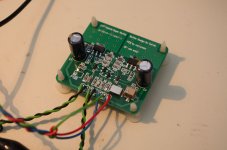
did a few more tests. Besides the CFP2 I also build the calvin buffer (all SMD).
The latter performs better in my setup😕 The calvin buffer with matched BF862 and SST4391 (unmatched) as cascodes shows almost no DC offset and I measure a THD below 0.0005% (390 Ohm load!) which is the residual of my soundcard (RME DIGI96).
The CFP2 has 200mV DC offset and can't be tuned (upper pot P2) below 0.005% THD. It shows higher third order distortion. I did not match the BJTs (BC807-40 as well as FZT751). I'll check the board again when I find the time (Calvin, any hint is welcome 😉).
Both will need heatsinks at least for the FZT. No thermal runaway but integrated "heatsinks" (copper area) gets quite hot (60-70 degrees C I guess). Will measure temperature later.
regards, Daniel
Hi all,
did a few more tests. Besides the CFP2 I also build the calvin buffer (all SMD).
The latter performs better in my setup😕 The calvin buffer with matched BF862 and SST4391 (unmatched) as cascodes shows almost no DC offset and I measure a THD below 0.0005% (390 Ohm load!) which is the residual of my soundcard (RME DIGI96).
The CFP2 has 200mV DC offset and can't be tuned (upper pot P2) below 0.005% THD. It shows higher third order distortion. I did not match the BJTs (BC807-40 as well as FZT751). I'll check the board again when I find the time (Calvin, any hint is welcome 😉).
Both will need heatsinks at least for the FZT. No thermal runaway but integrated "heatsinks" (copper area) gets quite hot (60-70 degrees C I guess). Will measure temperature later.
regards, Daniel
Hi,
the high Offset comes to a surprise.
In my sims I did also a MonteCarlo analysis with +-5% resistor tolerance of all collector/Drain and Emitter/Source resistors, replaced the lower Q4 from a BC807-40 to a -25 and stepped the Is and Vaf of the upper Q3 from 2E-13 to 3E-13 and 24 to 34 resp.
Offset stayed between +30mV and -40mV.
Offset lowered with lower Rtol. (+8mV to -5mV for +-1%) and rose with increased Rtol (+50mV to -60mV for +-10%).
Maybe one of the transistors or resistors is way off its value?
K2 was in sim always dominant.
jauu
Calvin
Last edited:
Thanks a lot for your comment calvin.
I also did some parameter studies (however by far not such a deep analysis) and was surprised by the offset and the THD figure (dominant K3). Rs are 0.5%
I'll check the board and parts for potential errors and report 😱
regards, Daniel
Hi,
the high Offset comes to a surprise.
In my sims I did also a MonteCarlo analysis with +-5% resistor tolerance of all collector/Drain and Emitter/Source resistors, replaced the lower Q4 from a BC807-40 to a -25 and stepped the Is and Vaf of the upper Q3 from 2E-13 to 3E-13 and 24 to 34 resp.
Offset stayed between +30mV and -40mV.
Offset lowered with lower Rtol. (+8mV to -5mV for +-1%) and rose with increased Rtol (+50mV to -60mV for +-10%).
Maybe one of the transistors or resistors is way off its value?
K2 was in sim always dominant.
jauu
Calvin
I also did some parameter studies (however by far not such a deep analysis) and was surprised by the offset and the THD figure (dominant K3). Rs are 0.5%
I'll check the board and parts for potential errors and report 😱
regards, Daniel
small Update
One of the FETs was obviously way off. After changing both FETs to new matched ones DC offset is now only 1.2mV. THD however is still "high" (0.0038%) and dominant 3rd (K2:-100dB, K3:-92dB). Any idea?
regards, Daniel
One of the FETs was obviously way off. After changing both FETs to new matched ones DC offset is now only 1.2mV. THD however is still "high" (0.0038%) and dominant 3rd (K2:-100dB, K3:-92dB). Any idea?
regards, Daniel
well, there's no symmetry 😱
Input signal 1kHz 8Vpp, load 390 Ohm
Upper half 20,6mApp
Lower half 1,3mApp
Used upper pot to tune for lowest K2 before. Now I changed the pot setting to halfway symmetric current swing which is the end setting (1k to V+, 0R to emitter of BC807, 10,8mA and 8,2mA). K3 reduced slightly from -92dB to -94dB but K2 is higher (-89dB, was -100dB before).
regards, Daniel
Hi,
around -90dB certainly is impressively low for such a simple Buffer feeding into such a lowohmic load. Wether the Calvin may be a few dB lower or not is rather of academic interest.
If there were a sonic difference I guess that one could tune both a bit by varying the degree of current modulation, hence altering the THD footprint.
It seems that depending sometimes the modulation degree cant be tuned to full symmetry. Varying the current distribution between input branch and output branch by varying R5/R10 (schem #190) and optionally varying the overall idle current with R6/R11 may help. In my sims the best results were achieved with equal resistor values R5=R10 = R6=R11. As lowest load impedance I use 300R singleended --> 600R balanced.
jauu
Calvin
jauu
Calvin
Hi,
edit:
This will also reduce overall idle, but not by much.
In my sims a good starting point was achieved with equal resistor values R5=R10 = R6=R11. With higher load impedances lower degrees of moduation are required. /snip
jauu
Calvin
edit:
snip/ The modulation degree rises if more current is routed through the JFET-branch and less through the bipolar branch. This is achieved by increasing R5/R10´s value....varying the overall idle current with R6/R11 may help.
This will also reduce overall idle, but not by much.
In my sims a good starting point was achieved with equal resistor values R5=R10 = R6=R11. With higher load impedances lower degrees of moduation are required. /snip
jauu
Calvin
- Home
- Source & Line
- Analog Line Level
- Preamp-Buffers - simple idea