Hi,
have You verified oscillation with an oscilloscope?
What's the frequency?
If its in the low- middle MHz range it could be the compensation caps.
But I don't assume that the compensation caps need to be changed.
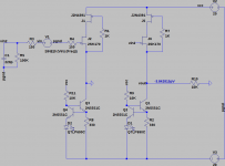
Another source could be the modulation of the current source.
Lifting a leg of the 220nF caps will make the lower half of the circuit a CCS, which is generally more stable than a modulated CS.
But I don't assume this to be the source of oscillation either.
I think Jazek has pointed towards the right direction, the supply.
I see two issues and suggest You download the DS from TI, priority on pages 10 and 23.
On page 10 the DS from TI describes which type and what amount of capacitance may be suitable.
Between Prereg and Reg I'd expect a low-esr cap of min. 1uF (see Fig. 49 for reference).
Larger Caps improve ripple rejection especially for higher load current values, but increase the regulator time constant.
Around 10uF should suffice.
I'd parallel a small ceramic (smd, X7R) to a standard lytic of 10uF-22uF to guarantee the required low impedance at HF.
But the 1uF (C4,6) used in Your supply could be enough already, if You short the 3k3 resistor (R6,11).
If the output caps C5,7 are no low-esr types, I' add small ceramics here too.
The second issue could be the two LEDs.
The regulator requires a certain minimum input-to-output voltage to work as regulator at all (Fig.12).
Adding a little headroom ~3V should be enough to ensure good regulator action.
Now the Prereg stands its sense input on the regulators through a resistor, but here it are the two LEDs.
I assume the designer wanted to achieve lower noise.
Add the ~1.25V of the LM317/337's reference voltage to the voltage drop over the LEDs (or resistors) and the sum should be higher than the minimal Vdiff(in-out).
The DS specs the adjustment pin current as 50uA typ.
While it is easy to generate suffucient voltage drop over a resistor with this low current, the voltage drop (Vf) of a LED might be just marginal or too low.
The LEDs should be high efficiency types (brightness specced at 1mA)
You should check, if the regulators In-Out voltage differential is high enough.
Of course the same applies to the Preregs.
Mods You may want to waste a thought on:
- adding caps and diodes to the Adj-inputs of the Regs to improve ripple rejection and protection (see Fig. 39)
- adding protection diodes from the Reg outputs to the Prereg inputs (Fig. 24)
jauu
Calvin
have You verified oscillation with an oscilloscope?
What's the frequency?
If its in the low- middle MHz range it could be the compensation caps.
But I don't assume that the compensation caps need to be changed.
Another source could be the modulation of the current source.
Lifting a leg of the 220nF caps will make the lower half of the circuit a CCS, which is generally more stable than a modulated CS.
But I don't assume this to be the source of oscillation either.
I think Jazek has pointed towards the right direction, the supply.
I see two issues and suggest You download the DS from TI, priority on pages 10 and 23.
On page 10 the DS from TI describes which type and what amount of capacitance may be suitable.
Between Prereg and Reg I'd expect a low-esr cap of min. 1uF (see Fig. 49 for reference).
Larger Caps improve ripple rejection especially for higher load current values, but increase the regulator time constant.
Around 10uF should suffice.
I'd parallel a small ceramic (smd, X7R) to a standard lytic of 10uF-22uF to guarantee the required low impedance at HF.
But the 1uF (C4,6) used in Your supply could be enough already, if You short the 3k3 resistor (R6,11).
If the output caps C5,7 are no low-esr types, I' add small ceramics here too.
The second issue could be the two LEDs.
The regulator requires a certain minimum input-to-output voltage to work as regulator at all (Fig.12).
Adding a little headroom ~3V should be enough to ensure good regulator action.
Now the Prereg stands its sense input on the regulators through a resistor, but here it are the two LEDs.
I assume the designer wanted to achieve lower noise.
Add the ~1.25V of the LM317/337's reference voltage to the voltage drop over the LEDs (or resistors) and the sum should be higher than the minimal Vdiff(in-out).
The DS specs the adjustment pin current as 50uA typ.
While it is easy to generate suffucient voltage drop over a resistor with this low current, the voltage drop (Vf) of a LED might be just marginal or too low.
The LEDs should be high efficiency types (brightness specced at 1mA)
You should check, if the regulators In-Out voltage differential is high enough.
Of course the same applies to the Preregs.
Mods You may want to waste a thought on:
- adding caps and diodes to the Adj-inputs of the Regs to improve ripple rejection and protection (see Fig. 39)
- adding protection diodes from the Reg outputs to the Prereg inputs (Fig. 24)
jauu
Calvin
Calvin, Jazek, thank you a lot for your advices.
The value of the filter resistor (3K3) in the shown schematic has only been a typo. I am of course using a 3R3 on my prototype PCB.
I need to take a closer look at the LED used.
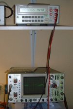
I will try and capture any oscillation on my oscilloscope this afternoon and will show an image of the output of the PSU as well.
Best regards - Rudi
The value of the filter resistor (3K3) in the shown schematic has only been a typo. I am of course using a 3R3 on my prototype PCB.
I need to take a closer look at the LED used.
I will try and capture any oscillation on my oscilloscope this afternoon and will show an image of the output of the PSU as well.
Best regards - Rudi
Attachments

Hi Rudi,
First measure the voltage difference between the in and out of the pre-regulators and the regulators, as Calvin suggested. You may want to replace the LEDs with resistors. Even if the regulator doesn't oscillate, it's a good idea to have it work properly.
First measure the voltage difference between the in and out of the pre-regulators and the regulators, as Calvin suggested. You may want to replace the LEDs with resistors. Even if the regulator doesn't oscillate, it's a good idea to have it work properly.
Gentlemen, I must apologize.
I am indeed measuring a AC-ripple of about 800µV on my PSU's rails.
I know that I can do it much better. I have recently built a TPR for a DAC that had a ripple of only <40µV.
Maybe the prototype's PCB-layout has been too poor.
I will improve it and will then report on my findings.
Best regards - Rudi
Attachments
Rudi,
Just to be sure that you have stable PSU in any condition I would suggest to replace single red LED you use in your PSU (as I can see at your pictures) with either blue/white one or use other voltage reference. Red LED has forward voltage around 1.8V and with 1.25V of internal reference voltage of LM3x7 you got just a bit above 3V difference In-Out for secondaty LM which is some condition may be too small. White or blue LED has (if I remember correctly...) 2.8-3V forward voltage so this will put your circuit on safe side.
I saw some elaborations somewhere that solution with LED (or any other voltage reference) is better then single resistor (720 ohm as per datasheet) but you have to ensure to meet this minimum IN-Out voltage difference condition.
rgds
-jacek
Using 3-pin regulators off-piste: part 4
I always use this last schematic from here, with good results.
Cheers!
I always use this last schematic from here, with good results.
Cheers!
Hi,
I suggest strongly to stick to the DS.
There's no good reason here to use a LED instead of the resistor, because there will be by far not enough current that the LED will generate its specified Vf or stays well within the linear part of its Vf/I curve.
Second, omit with the series-to-the-cap resistor.
If the DS states that the Reg requires low esr caps at the output to work properly, it'd be a really dumb idea to add any resistance at all. 🙄
If a bit of esr is required than simply use a different (cheaper) cap.
You know DS are a present of the manufacturers to us users to prevent us from making failures or stupid things like using wrong or falsly dimensioned external parts 😉
jauu
Calvin
Hello,
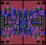
I started to use Eagle LT, and as a first learning project I did a layout for a stereo Calvin Buffer. I would be happy if someone cared to give an opinion.
The layout is based on the schematic of Alfred from the paradise-buffer group buy. There is a input filter added. It uses SMD parts for the passive components and is for stereo application.
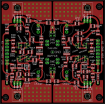
However, I had some design considerations in mind, that make it not the tiniest/most efficient layout you can do:
I wanted to use the 1210 SMD size, for easier handling without a magnifying-glass.
The transistors are through hole, so I can use the matched transistors from the group-buy. They are grouped on a small area, so they can be heatsinked together for thermal coupling.
The star ground should be the main ground point in my application. I used a star ground with sections for the left and right signal ground, and positive and negative voltage supply. The rest of the bottom layer acts as heatsink. There are several inputs for signal-GND and power-GND.
The multiple inputs allow for flexible usage, but it is intended for salas shunt regulators with +/- sensing connections.
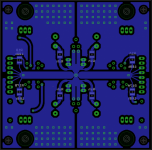
I am not quite sure about the connection of the salas reg. Since it is sensitive to load capacitance, a common input rail filter configuration involes a low capacitance (ca 1uF) film cap with artificial ESR.
A second variant would be high capacitance electrolytic cap, but with serial R (a few Ohm) as used for example in the JG-filter buffer.
I am not sure about which way to go here. I don´t own an oszilloscope and I would be glad for some advice.
The board can take both solutions.
Here are some pics, you have to open them in a new tab. Feel free to leave feedback. Thank you 🙂
I started to use Eagle LT, and as a first learning project I did a layout for a stereo Calvin Buffer. I would be happy if someone cared to give an opinion.
The layout is based on the schematic of Alfred from the paradise-buffer group buy. There is a input filter added. It uses SMD parts for the passive components and is for stereo application.
However, I had some design considerations in mind, that make it not the tiniest/most efficient layout you can do:
I wanted to use the 1210 SMD size, for easier handling without a magnifying-glass.
The transistors are through hole, so I can use the matched transistors from the group-buy. They are grouped on a small area, so they can be heatsinked together for thermal coupling.
The star ground should be the main ground point in my application. I used a star ground with sections for the left and right signal ground, and positive and negative voltage supply. The rest of the bottom layer acts as heatsink. There are several inputs for signal-GND and power-GND.
The multiple inputs allow for flexible usage, but it is intended for salas shunt regulators with +/- sensing connections.
I am not quite sure about the connection of the salas reg. Since it is sensitive to load capacitance, a common input rail filter configuration involes a low capacitance (ca 1uF) film cap with artificial ESR.
A second variant would be high capacitance electrolytic cap, but with serial R (a few Ohm) as used for example in the JG-filter buffer.
I am not sure about which way to go here. I don´t own an oszilloscope and I would be glad for some advice.
The board can take both solutions.
Here are some pics, you have to open them in a new tab. Feel free to leave feedback. Thank you 🙂
An externally hosted image should be here but it was not working when we last tested it.
An externally hosted image should be here but it was not working when we last tested it.
An externally hosted image should be here but it was not working when we last tested it.
I completed two board of calvin buffer and both working. I used Phillips BD140 as the bjt output with C0G 100pf. Is it ok?
Hi,
congrats and I hope You'll like them 😉
jauu
Calvin
Yeah, I liked it a lot. It is for my amp and it did its job quite well.
Delayed output muting and un-muting for Calvin Buffer
Hi everyone,
I hope I've found the right thread where all of the Calvin Buffer enthusiasts congregate. Google search and diyAudio search pointed here, and that's why I'm posting.
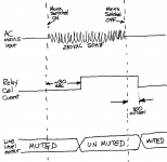
I helped out a friend who is building a Calvin Buffer, and I thought other people might be interested too. My friend wants to mute the output of his Calvin Buffer for the first approx. 30 seconds after power-on. He does not want any turn-on thumps and gradually-meandering DC offsets, to escape from the Calvin Buffer and get into the power amp & speakers. So I built him a little circuit. I've also placed it into the public domain; I'm giving away the schematic and the PCB layout ("Gerber files") for free. The way it works is diagrammed in the attached drawing.
Output is muted for 30 seconds after power on, then unmuted. Output remains un-muted for 0.8 seconds after power off, then muted. Both of these delays can be adjusted.
Hope this is helpful,
Mark Johnson
Hi everyone,
I hope I've found the right thread where all of the Calvin Buffer enthusiasts congregate. Google search and diyAudio search pointed here, and that's why I'm posting.
I helped out a friend who is building a Calvin Buffer, and I thought other people might be interested too. My friend wants to mute the output of his Calvin Buffer for the first approx. 30 seconds after power-on. He does not want any turn-on thumps and gradually-meandering DC offsets, to escape from the Calvin Buffer and get into the power amp & speakers. So I built him a little circuit. I've also placed it into the public domain; I'm giving away the schematic and the PCB layout ("Gerber files") for free. The way it works is diagrammed in the attached drawing.
Output is muted for 30 seconds after power on, then unmuted. Output remains un-muted for 0.8 seconds after power off, then muted. Both of these delays can be adjusted.
- 2 seconds < Power On Muting < 40 seconds
- 0.2 seconds < Power Off Muting < 4 seconds
Hope this is helpful,
Mark Johnson
Attachments
Hi,
nice little protection - well not soo little actually, compared to a stereo-set of SMD-PCBs of the Buffer. 😉
In #278 I presented a DC-servo circuit for the Buffer, that may reduce Offset settling-time considerably and that omits with the Offset-Trimpot.
The current-modulation pot in the upper half of the Buffer isn´t mandatory either, so that one could omit with pots alltogether, apart from an optional volume-pot of course.
jauu
Calvin
ps:
... didn´t receive a board

nice little protection - well not soo little actually, compared to a stereo-set of SMD-PCBs of the Buffer. 😉
In #278 I presented a DC-servo circuit for the Buffer, that may reduce Offset settling-time considerably and that omits with the Offset-Trimpot.
The current-modulation pot in the upper half of the Buffer isn´t mandatory either, so that one could omit with pots alltogether, apart from an optional volume-pot of course.
jauu
Calvin
ps:
Too bad I´m just a enthusiastic Calvin ....The board worked well, and I have shipped it off to my buddy the Calvin Buffer enthusiast.
... didn´t receive a board
Yes, the variable delay muting board uses thru-hole components and relaxed component spacing. I knew I couldn't make it 5x5 (the size of the transformer alone!) or 5x10, so I aimed for 5x20. These are the max-sizes for the first three, pricing tiers at far east PCB fabs.
Please feel free to lay out your own board using that circuit schematic, and partly-SMD, partly-thru-hole components. I was unable to find a dual-primary transformer with 12VAC secondary, in the teeny tiny 1VA size; but maybe you will succeed. The 2.4VA transformer used here is bigger than electrically necessary. Similarly please feel free to replace the output connectors with something smaller. I considered plain old holes (wire-soldered-to-board), but my "customer" (Calvin Buffer friend) requested these.
Anybody who wants one of these boards can send the Gerber files I provided, to a PCB fab. Attached below are current price quotations for this board, shipped to Europe (Germany). This is what you pay to get TEN copies of the PCBoard. Go to (the pcbshopper.com website) and get a quote for YOUR shipping destination and YOUR currency. Tell the website you want 2 layers copper, 2 layers silkscreen, Qty=10, 4.9cmX19cm.
I have a small number of blank boards left over after my little construction effort, which I would be happy to send to other DIYers for USD 10 (ship to USA+Can+Mex) or USD 15 (rest of world) via PayPal, and discounted price if you mail me a USD-denominated check instead of PayPal. Some of my remaining boards are green and others are red.
Attachments

Yes, the variable delay muting board uses thru-hole components and relaxed component spacing. I knew I couldn't make it 5x5 (the size of the transformer alone!) or 5x10, so I aimed for 5x20. These are the max-sizes for the first three, pricing tiers at far east PCB fabs.
Please feel free to lay out your own board using that circuit schematic, and partly-SMD, partly-thru-hole components. I was unable to find a dual-primary transformer with 12VAC secondary, in the teeny tiny 1VA size; but maybe you will succeed. The 2.4VA transformer used here is bigger than electrically necessary. Similarly please feel free to replace the output connectors with something smaller. I considered plain old holes (wire-soldered-to-board), but my "customer" (Calvin Buffer friend) requested these.
Anybody who wants one of these boards can send the Gerber files I provided, to a PCB fab. Attached below are current price quotations for this board, shipped to Europe (Germany). This is what you pay to get TEN copies of the PCBoard. Go to (the pcbshopper.com website) and get a quote for YOUR shipping destination and YOUR currency. Tell the website you want 2 layers copper, 2 layers silkscreen, Qty=10, 4.9cmX19cm.
I have a small number of blank boards left over after my little construction effort, which I would be happy to send to other DIYers for USD 10 (ship to USA+Can+Mex) or USD 15 (rest of world) via PayPal, and discounted price if you mail me a USD-denominated check instead of PayPal. Some of my remaining boards are green and others are red.
Thank you for the usefull info.
I wonder why there is such a difference in prices between china providers.... something to do with quality ?
I suspect a lot of the very cheap components are rejects that don't pass well set up inspection systems.
They somehow reach a market at miniscule prices and then get labeled/relabeled to be sold on by the fraudsters.
They somehow reach a market at miniscule prices and then get labeled/relabeled to be sold on by the fraudsters.
Hi,
I have two calvin buffer running at the moment and very happy with the results. But I had a visit on this link
RJM Audio - Szekeres VE Headphone Buffer
and combine it with version B. I come up with the ideal of a buffer. It sim well, but I know there is a different between SIM and REALITY. Could anyone point up its problem?
Attachments
- Home
- Source & Line
- Analog Line Level
- Preamp-Buffers - simple idea