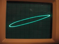
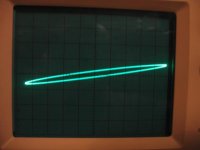
Non-linear phase shift on 10 kHz is well visible.
More interesting pictures are when input goes on X, output on Y.
More interesting pictures are when input goes on X, output on Y.
It was aimed here to force current into output (X axis) and observe voltage drop (Y axis). The images are at higher bias (like 350mA). In case of "cold" bias (50mA or so), the nonlinearities are shifted closer to [0,0] point.
pma:
any plans to update the jfet distortion pages of your website with pre standard two preamp research?
mlloyd1
any plans to update the jfet distortion pages of your website with pre standard two preamp research?
mlloyd1
Hi Pavel;
here is one more idea: to eliminate batteries from a guitar pedal I powered it from pair of current sources; actually there was one current source and couple of current mirrors from plus and minus rails. The pedal contained a bi-polar shunt regulator only, and was connected by one shielded wire and one naked pair for both plus and minus. Output dynamic resistance between ground and both powering wires was huge.
This trick may be used to power your MC preamp as well, with no ground connection of the power supply at all.
pma:
any plans to update the jfet distortion pages of your website with pre standard two preamp research?
mlloyd1
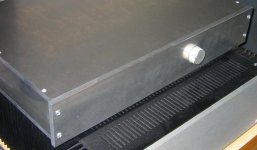
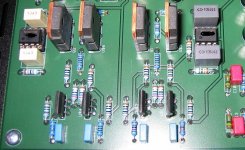
Unfortunately I have not updated the pages yet 😉. But I have some partial PCB photos. These 2SK389/2SJ109 are great sounding parts.
Attachments
pma:
looks good - both spectrum and the unit's pcb layout.
you must have a lot of those hitachi mosfets 😉
mlloyd1
looks good - both spectrum and the unit's pcb layout.
you must have a lot of those hitachi mosfets 😉
mlloyd1
Thank you 🙂. I wish I had such a stock of 2SK389/2SJ109 😀
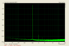
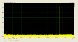
Regarding spectrum, it is at the limit of my measurement possibilities. Now I am showing CCIF IMD of the preamp.
Unfortunately, I have not found any correlation between THD, IMD, square wave responses and resulting sound. I have a bipolar preamp and JFET-MOSFET preamp that measure quite same in all known parameters and measurements, but they still sound very different ... 😎
Attachments
pma, you anticipated my next question! i just wasn't sure if the bipolar preamp you had was constructed in a chassis of the same performance level as that of the pre standard two, to make sure it would be a fair comparison.
mlloyd1
mlloyd1
I have recently tested the bipolar preamplifier vs. the FET preamplifier both in a same conventional, 1U 440mm case. The sonic difference is easily audible.
Regarding the milled Al case - compared to the conventional case, it makes some difference. I would say like a difference between link level cables. That means, the difference in sound of bipolar vs. fet preamplifier is higher than the contribution of the milled Al case.
Regarding the milled Al case - compared to the conventional case, it makes some difference. I would say like a difference between link level cables. That means, the difference in sound of bipolar vs. fet preamplifier is higher than the contribution of the milled Al case.
- Status
- Not open for further replies.
- Home
- Amplifiers
- Solid State
- pre standard two preamp, and development of measurement methods