Would the driver ic’s cause this or should I look for something else that’s messing the drive up
Q4,75 the source legs are grounded .
Not sure why Q2 doesn’t show loading since the cap is soldered between gate and source .
Not sure why Q2 doesn’t show loading since the cap is soldered between gate and source .
For those 2 FETs, bridge legs 2 and 3 and re-check the drive signals on the 2 FETs that didn't show their loaded signals as expected.
Please (and this applies to anyone who needs repair help) use your sig line to list all equipment you have, editing it as equipment changes. Include the model numbers.
Top of page, menu USER CP >> EDIT SIGNATURE
Oscilloscope (yes or no)
Multimeter(s)
Type of signal source (grounded RCA shields preferred).
Soldering iron
Desoldering pump
Power supply
2 ohm current limiting resistor (hollow cylindrical ceramic 100w preferred)
Top of page, menu USER CP >> EDIT SIGNATURE
Oscilloscope (yes or no)
Multimeter(s)
Type of signal source (grounded RCA shields preferred).
Soldering iron
Desoldering pump
Power supply
2 ohm current limiting resistor (hollow cylindrical ceramic 100w preferred)
A differential input uses two inputs to produce a single waveform. The simplest way to get a differential input is to use a differential probe. A differential probe has two signal leads and a mixer amplifier built into it. It feeds the scope a normal signal (a composite of the two signals input into the differential probe). The problem with differential probes is that they're expensive. The cheapest ones are about $60 used and they can cost more than $3000.
The alternative is to use two scope probes and and both inputs of your oscilloscope. This is how you have to set up your scope:
Two probes
Both scope inputs used
Input set to add
Both channels set to DC coupling
Both vertical amps set to the same voltage
Ch2 input set to invert
Bandwidth limited (works best for most measurements in car amps)
Trace aligned to the reference line on the scope's display
Ground leads for both probes connected together
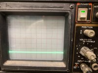
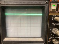
After setting up the scope, you need to confirm that it's working as it should. With the vertical amp set to 5v/div, touching the probe that's connected to Ch1 to the positive terminal of your 12v power supply should make the trace deflect about 2.5 divisions up from the reference (like it always does, seen below). Doing the same with the probe connected to Ch2 should make the trace deflect down about 2.5 divisions. Touching both probes to the positive terminal of the 12v power supply should cause no deflection. If it does, something isn't right.
I know that this may not be as simple as the isolated scope but if you take the time to learn it one time (even if it takes an hour or more of your time), you have that knowledge and this tool to use for the rest of the time you need to use a scope. Using the analog scope will give you much larger and cleaner waveforms.
The alternative is to use two scope probes and and both inputs of your oscilloscope. This is how you have to set up your scope:
Two probes
Both scope inputs used
Input set to add
Both channels set to DC coupling
Both vertical amps set to the same voltage
Ch2 input set to invert
Bandwidth limited (works best for most measurements in car amps)
Trace aligned to the reference line on the scope's display
Ground leads for both probes connected together
After setting up the scope, you need to confirm that it's working as it should. With the vertical amp set to 5v/div, touching the probe that's connected to Ch1 to the positive terminal of your 12v power supply should make the trace deflect about 2.5 divisions up from the reference (like it always does, seen below). Doing the same with the probe connected to Ch2 should make the trace deflect down about 2.5 divisions. Touching both probes to the positive terminal of the 12v power supply should cause no deflection. If it does, something isn't right.
I know that this may not be as simple as the isolated scope but if you take the time to learn it one time (even if it takes an hour or more of your time), you have that knowledge and this tool to use for the rest of the time you need to use a scope. Using the analog scope will give you much larger and cleaner waveforms.
Wondering if I could have damaged one of the 4081’s when the amp few excessive current due to the SG3525 being defective ?
I removed all fets and both 4081’s are out of circuit right now
I removed all fets and both 4081’s are out of circuit right now
Ok I confirmed that the ic’s are defective .
I used the HIP4081AIPZ to replace the originals .
Before I order new ones are these ok to use in the amp or do I need the non Z version ?
Wondering this since on digikey it says 4081AIPZ is a half bridge and the 4081AIP is full bridge
I used the HIP4081AIPZ to replace the originals .
Before I order new ones are these ok to use in the amp or do I need the non Z version ?
Wondering this since on digikey it says 4081AIPZ is a half bridge and the 4081AIP is full bridge
Last edited:
I replaced the HIP4081’s put them in sockets this time .
I still get no drive on Q2 and Q12 the trace just deflects
Any ideas what might cause this
I still get no drive on Q2 and Q12 the trace just deflects
Any ideas what might cause this
I have to get another probe the other one I had a s a spare is no good I just tried it out and it does nothing
- Home
- General Interest
- Car Audio
- PPI PC21400.2