You know it's tough when you can't get a straight flare to fold right! What happens if you shorten the length so more to get rid of that wasted space? Remember, f3 only needs to be 38hz.
I think bigger cross section and shorter length will gain efficiency and create an easier fold. To bad HR doesn't work on droids.
Hi BP1Fanatic,
Post #242: "... bigger cross section and shorter length will gain efficiency and create an easier fold..."
The problem seems to be that we are pushing the driver more and more away from its natural range. My experiments simulating/drawing/simulating indicate to me, that the reduced cross-section provides a bit of needed control.
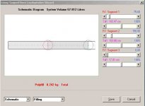
This enclosure type is a little touchy for path length dimensions, so you have to draw what you simulate, otherwise it's just a simulation. The filling is an integral part of the design, and thanks to David McBeans Hornresp we can now do a pretty good job of predicting the outcome.
Doubling the cross-section, and shortening the path lengths I end up w/ a box more than twice as big, and gain about 2dB. So for me the trade-off would be going w/ the smaller box.
I'll add the smallest box sofar below, I tried to simplify the fold while still shooting for a box inside of 30x30x14in. I added the necessary additional cross-section for areas which will need bracing; if other bracing is added, it should also be accounted for. This is the one I would build (I like the relatively small box.)
Regards,
Post #242: "... bigger cross section and shorter length will gain efficiency and create an easier fold..."
The problem seems to be that we are pushing the driver more and more away from its natural range. My experiments simulating/drawing/simulating indicate to me, that the reduced cross-section provides a bit of needed control.
This enclosure type is a little touchy for path length dimensions, so you have to draw what you simulate, otherwise it's just a simulation. The filling is an integral part of the design, and thanks to David McBeans Hornresp we can now do a pretty good job of predicting the outcome.
Doubling the cross-section, and shortening the path lengths I end up w/ a box more than twice as big, and gain about 2dB. So for me the trade-off would be going w/ the smaller box.
I'll add the smallest box sofar below, I tried to simplify the fold while still shooting for a box inside of 30x30x14in. I added the necessary additional cross-section for areas which will need bracing; if other bracing is added, it should also be accounted for. This is the one I would build (I like the relatively small box.)
Regards,
Attachments
-
lawbiding_JBL_GTO_1214_T_QWP_3D_long_L12.pdf50.8 KB · Views: 146
-
 GTO_1214_T_QWP_3D_long_L12_Wizard_Schematic.jpg18.1 KB · Views: 268
 -
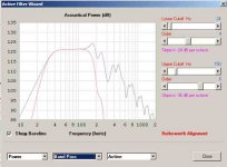 GTO_1214_T_QWP_3D_long_L12_Wizard_filtered_SPL.jpg20.4 KB · Views: 277
 -
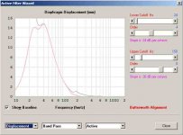 GTO_1214_T_QWP_3D_long_L12_Wizard_filtered_Displacement.jpg20.4 KB · Views: 272
 -
law_qw3d.txt992 bytes · Views: 88
Hi BP1Fanatic,
Post #242: "... bigger cross section and shorter length will gain efficiency and create an easier fold..."
The problem seems to be that we are pushing the driver more and more away from its natural range. My experiments simulating/drawing/simulating indicate to me, that the reduced cross-section provides a bit of needed control.
This enclosure type is a little touchy for path length dimensions, so you have to draw what you simulate, otherwise it's just a simulation. The filling is an integral part of the design, and thanks to David McBeans Hornresp we can now do a pretty good job of predicting the outcome.
Doubling the cross-section, and shortening the path lengths I end up w/ a box more than twice as big, and gain about 2dB. So for me the trade-off would be going w/ the smaller box.
I'll add the smallest box sofar below, I tried to simplify the fold while still shooting for a box inside of 30x30x14in. I added the necessary additional cross-section for areas which will need bracing; if other bracing is added, it should also be accounted for. This is the one I would build (I like the relatively small box.)
Regards,
Tb46
I will go with this one as you suggest and I like the size.
Thanks for the drawing.
Tb46
I will go with this one as you suggest and I like the size.
Thanks for the drawing.
Something to bear in mind: HornResp, from what I heard, does not include the effect of losses. This can result in the actual response at lower frequencies being a bit less then that predicted, the actual difference being dependent on a number of factors. See for example the image below which compares a sim of a medium-Q driver in vented box with no losses (the blue curve) with one taking the impact of losses into effect (the red curve).
Attachments
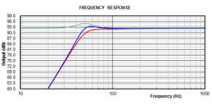
Something to bear in mind: HornResp, from what I heard, does not include the effect of losses. This can result in the actual response at lower frequencies being a bit less then that predicted, the actual difference being dependent on a number of factors. See for example the image below which compares a sim of a medium-Q driver in vented box with no losses (the blue curve) with one taking the impact of losses into effect (the red curve).
Brian
Thanks for the heads up.
Hi Y'all,
I'm happy that we have a final fold for lawbiding. He'll be able to tune the enclosure using a bit more or less filling, that will help to account for the losses. The rest of the tuning will be in the HP and Lp filters to make it cooperate w/ the rest of the system.
Regards,
I'm happy that we have a final fold for lawbiding. He'll be able to tune the enclosure using a bit more or less filling, that will help to account for the losses. The rest of the tuning will be in the HP and Lp filters to make it cooperate w/ the rest of the system.
Regards,
Hi Y'all,
I'm happy that we have a final fold for lawbiding. He'll be able to tune the enclosure using a bit more or less filling, that will help to account for the losses. The rest of the tuning will be in the HP and Lp filters to make it cooperate w/ the rest of the system.
Regards,
Thanks Tb46
I can't to build this one.
Tb46 can you put the drawing and layout measurements in fraction inches form.
Thanks
Last edited:
Hi lawbiding,
We live to please: 🙂
Just lay it out on a side panel. As it says in the drawing, the front (driver side) and back ducts are 4" high to compensate for the bracing needed to stiffen the panels, and to make them removable; all other ducts are 3-3/4" high. The area around the driver, and in the back of the driver you'll have to work out as you go a long.
Regards,
Attachments
Hi lawbiding,
We live to please: 🙂
Just lay it out on a side panel. As it says in the drawing, the front (driver side) and back ducts are 4" high to compensate for the bracing needed to stiffen the panels, and to make them removable; all other ducts are 3-3/4" high. The area around the driver, and in the back of the driver you'll have to work out as you go a long.
Regards,
You are too kind. 🙂 I prefer decimal format myself for construction.
This is a cool and compact box.
Hi lawbiding,
We live to please: 🙂
Just lay it out on a side panel. As it says in the drawing, the front (driver side) and back ducts are 4" high to compensate for the bracing needed to stiffen the panels, and to make them removable; all other ducts are 3-3/4" high. The area around the driver, and in the back of the driver you'll have to work out as you go a long.
Regards,
Tb46
Thanks for being so kind and helpful with this project 😀
I am once again stuck trying to figure out a part of the drawing. I tried but I cant get it right, everything else falls in to place except this one area.


Great progress! I would stick a brace block in the channel between the braces on either side of the channel - this will give a mechanically much stronger brace as if you had a solid brace all the way thru. Same with a small block bear mouth channel.
Lawbiding, you don't play around when it comes to knocking out these builds!
Nope.
Hi lawbiding,
It's good that you redraw these before cutting wood.
I'll attach an error correction suggestion. I would also add a board @ S1 to correct the L12 length increase.
A note to the baffle board (the three boards the speaker is mounted to), the should all three go all the way to the bottom board, the immediate mounting board at the speaker would have only a straight sided hole, and the other two boards would be opened up @ about a 45° angle.
Hope that was the only error in the drawing.
Regards,
Attachments
Hi lawbiding,
It's good that you redraw these before cutting wood.
I'll attach an error correction suggestion. I would also add a board @ S1 to correct the L12 length increase.
A note to the baffle board (the three boards the speaker is mounted to), the should all three go all the way to the bottom board, the immediate mounting board at the speaker would have only a straight sided hole, and the other two boards would be opened up @ about a 45° angle.
Hope that was the only error in the drawing.
Regards,
Tb46 thanks
I will look over it before I start cutting.
- Home
- Loudspeakers
- Subwoofers
- PP Slot Loaded Sub with Alpine SWR 12D2