Lawbiding,
Good to hear from you - wondering what happened to you because you are normally very fast. Hope you feel better soon. Nice work and great progress - thanks for sharing. Don't forget to add bracing to the inside of the big chambers. Add some holey brace panels to break up the longitudinal standing waves in the back chamber.
Where in the cabinet do I add the bracings?
Last edited:
I think you have a good sense from your last project - it's not exact just make sure there aren't any spans longer than 6 or 8 in that goes unbraced. Tb46 may give you a nice suggested bracing plan 😀
Hi Y'all,
Great to see someone making progress. 🙂 How do the drivers fit, screws, etc? Keep the pictures coming.
Things around here have been a bit hectic lately. Anyway, some bracing suggestions:
Regards,
Tb46
Thank for the bracing suggestions.
I build the cabinet using the simplified port.

Hi xrk971,
Lawbiding asked for a TH for the JBL GTO 1214 for automotive use w/ a low end of about 38Hz. Hope you don't mind if I post it in this thread to keep the lawbinding projects together. Anyway, I'll keep it short, filling is optional:
Regards,
P.S.: A simple QWP would be a lot smaller, and easier to build. I haven't drawn one up yet.
Attachments
Last edited:
Tb46,
That is a nice design - big box though. I think lawbiding was asking for 38Hz to 150Hz range coverage which this TH doesn't quite go up high to. Not too many TH's can. A FLH can though - just bigger.
That is a nice design - big box though. I think lawbiding was asking for 38Hz to 150Hz range coverage which this TH doesn't quite go up high to. Not too many TH's can. A FLH can though - just bigger.
Hi xrk971,
Lawbiding asked for a TH for the JBL GTO 1214 for automotive use w/ a low end of about 38Hz. Hope you don't mind if I post it in this thread to keep the lawbinding projects together. Anyway, I'll keep it short, filling is optional:
Regards,
P.S.: A simple QWP would be a lot smaller, and easier to build. I haven't drawn one up yet.
Thanks guys for coming through again for me.
Tb46
What is the difference between a TH and a QWP in design and output? How smaller would the QWP be.
@Xrk971
A folded horn interesting.
Last edited:
Hi lawbiding,
Post #228: "...What is the difference between a TH and a QWP in design and output? How smaller would the QWP be."
The TH has a horn shaped duct, that expands from throat to mouth. The QWP is also a 1/4 wave resonator, but w/ constant cross-section. See the attached example for details.
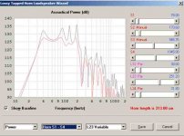
I forgot about the 150Hz, to get there you'll have to give up some SPL, and change the location of the driver in the duct, see attached Hornresp example QWP#2_long_L12. Here the driver is not placed @ the ends of the duct, but about in the middle.
Just as a note, the GTO 1214 wants to go lower, as in the Kraken THs by Petter Persson http://www.diyaudio.com/forums/subwoofers/160879-build-your-own-2x12-th-kraken-212-th.html , but, the box will get bigger fast. To get the upper range to 150Hz in a TH you'd have to add 1/4-wave tubular resonators to cancel out the two big upper peaks. Maybe X can show you how that is done in AkAbak.
I'll attach a QWP drawing, and Hornresp simulations for the long L12 and the short L12 QWPs. You can find your sweet spot for a Hornresp simulation should you go w/ one of these, or just go w/ mine.
Regards,
Post #228: "...What is the difference between a TH and a QWP in design and output? How smaller would the QWP be."
The TH has a horn shaped duct, that expands from throat to mouth. The QWP is also a 1/4 wave resonator, but w/ constant cross-section. See the attached example for details.
I forgot about the 150Hz, to get there you'll have to give up some SPL, and change the location of the driver in the duct, see attached Hornresp example QWP#2_long_L12. Here the driver is not placed @ the ends of the duct, but about in the middle.
Just as a note, the GTO 1214 wants to go lower, as in the Kraken THs by Petter Persson http://www.diyaudio.com/forums/subwoofers/160879-build-your-own-2x12-th-kraken-212-th.html , but, the box will get bigger fast. To get the upper range to 150Hz in a TH you'd have to add 1/4-wave tubular resonators to cancel out the two big upper peaks. Maybe X can show you how that is done in AkAbak.
I'll attach a QWP drawing, and Hornresp simulations for the long L12 and the short L12 QWPs. You can find your sweet spot for a Hornresp simulation should you go w/ one of these, or just go w/ mine.
Regards,
Attachments
-
law_qwp2.txt994 bytes · Views: 84
-
law_qwp.txt985 bytes · Views: 74
-
 GTO_1214_QWP#2_long_L12_Wizard_filtered_SPL.jpg20.8 KB · Views: 106
 -
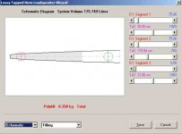
 GTO_1214_QWP#2_long_L12_Wizard_Schematic.jpg17.5 KB · Views: 222
 -
 GTO_1214_QWP_short_L12_Wizard_filtered_SPL.jpg21.4 KB · Views: 236
 -
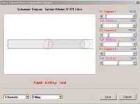
 GTO_1214_QWP_short_L12_Wizard_Schematic.jpg17.5 KB · Views: 247
 -
lawbiding_JBL_GTO_1214_QWP_short_L12.pdf21.8 KB · Views: 116
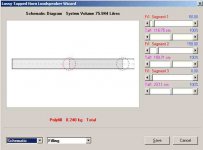
Hi lawbiding,
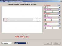
This is an update for the "long L12" QWP (with the driver in the middle). There are some changes in the individual section length. (I also noted some errors in the last drawing, but we'll take a closer look @ it if you decide to build it or this one.)
Regards,
This is an update for the "long L12" QWP (with the driver in the middle). There are some changes in the individual section length. (I also noted some errors in the last drawing, but we'll take a closer look @ it if you decide to build it or this one.)
Regards,
Attachments
Hi lawbiding,
This is an update for the "long L12" QWP (with the driver in the middle). There are some changes in the individual section length. (I also noted some errors in the last drawing, but we'll take a closer look @ it if you decide to build it or this one.)
Regards,
Tb46
When I get back to my computer I will punch these numbers in to horn response on let you know.
I like the layout of the qwp it look simple to build.
Thanks
Tb46
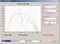
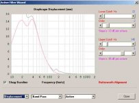
I will go with this one that is attach below. I like the frequency graph although it does not go up to a 150hz


Thanks
I will go with this one that is attach below. I like the frequency graph although it does not go up to a 150hz
Thanks
Last edited:
Tb46
I will go with this one that is attach below. I like the frequency graph although it does not go up to a 150hz
I'd be worried about that steep and deep notch in its output above 100 Hz
The long pipe looks interesting, though I think it can be optimized a bit further - there's s bit of wasted space in it.
Hi everyone
Thanks for chipping in on this project. My gold is to build a sub with a high output from 38hz to 80hz are higher if possible. I dont have any experience with qwp or tapped horn, so if I could get some feed back on which design I should go with that would be great. From what I read tapped horn have a higher output than some design.
The maximum size cabinet I am looking for is 30*30*14 Inches.
Thanks guys.
Hi....FYI:
b🙂
Hi Bjorno
The frequency output of this one is too
Low. This cabinet is to be use in a van.
Thanks
Last edited:
Just more thoughts to chew on.
Hi Y'all,
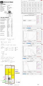
I like bjorno's example (Post #235) too, and he calls it correctly T-QWP (the T is for tapped); naturally, as he is one of the masters of this type of enclosure. Mine from Post #230 is quite similar, it has a different fold, and a smaller duct cross-section.
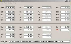
Since then I have reduced the duct cross-section in the drawing/simulation even more (303.9cm^2-same width w/ 3.75"duct height), and tried to reduce internal volume waste, but when we increase the compression ratio (reduce cross-section) we also loose SPL, and it becomes more difficult to get the driver in the box (the multiple boards are bjorno's idea: Thanks); still this one would get you to 120dB in 1 x Pi, more than I would want to be subjected to. I also like the softer lower roll-off (2nd order HP filter). And the box is smaller.
I'll attach the data on that one, and then I'll run, or I'll be in trouble. 🙂
Regards,
P.S.: I hope, that somebody who knows what he is doing would look this over, and help w/ the direction of this design.
Hi Y'all,
I like bjorno's example (Post #235) too, and he calls it correctly T-QWP (the T is for tapped); naturally, as he is one of the masters of this type of enclosure. Mine from Post #230 is quite similar, it has a different fold, and a smaller duct cross-section.
Since then I have reduced the duct cross-section in the drawing/simulation even more (303.9cm^2-same width w/ 3.75"duct height), and tried to reduce internal volume waste, but when we increase the compression ratio (reduce cross-section) we also loose SPL, and it becomes more difficult to get the driver in the box (the multiple boards are bjorno's idea: Thanks); still this one would get you to 120dB in 1 x Pi, more than I would want to be subjected to. I also like the softer lower roll-off (2nd order HP filter). And the box is smaller.
I'll attach the data on that one, and then I'll run, or I'll be in trouble. 🙂
Regards,
P.S.: I hope, that somebody who knows what he is doing would look this over, and help w/ the direction of this design.
Attachments
-
lawbiding_JBL_GTO_1214_T_QWP_3B_long_L12.pdf28.2 KB · Views: 125
-
 GTO_1214_T_QWP_3B_long_L12_Wizard_Schematic.jpg18.2 KB · Views: 232
 -
 GTO_1214_T_QWP_3B_long_L12_Wizard_filtered_SPL.jpg19.6 KB · Views: 204
 -
 GTO_1214_T_QWP_3B_long_L12_Wizard_filtered_Displacement.jpg19.3 KB · Views: 203
 -
law_qw3b.txt992 bytes · Views: 81
- Home
- Loudspeakers
- Subwoofers
- PP Slot Loaded Sub with Alpine SWR 12D2