Hi lawbiding,
Post #178: "...Would adding a plate amp change anything on the drawing."
Yes, it would change the internal volume, and it would be difficult to account for that without starting over. Maybe you can add a rear extension?
Regards,
Post #178: "...Would adding a plate amp change anything on the drawing."
Yes, it would change the internal volume, and it would be difficult to account for that without starting over. Maybe you can add a rear extension?
Regards,
Hi lawbiding,
Post #178: "...Would adding a plate amp change anything on the drawing."
Yes, it would change the internal volume, and it would be difficult to account for that without starting over. Maybe you can add a rear extension?
Regards,
Good idea.lol
Xrk971
I will be using the Mcm two 55-2421 driver which is rated 4 ohm and series them to 8 ohms
My mistake, I forgot that they were 4ohm. So then we are at 47 volts rms at 8ohms which is 250 watts - I think that is the thermal max rating.
Hi lawbiding,
Post #178: "...Would adding a plate amp change anything on the drawing."
Yes, it would change the internal volume, and it would be difficult to account for that without starting over. Maybe you can add a rear extension?
Regards,
If you went with a class D IRS2092 MOSFET amp, they take very little volume. Their power supply is another story.
For example:
2x250W IRS2092 Class-D Amplifier Board
But you will need a dual rail power supply. Either some SMPS Meanwells or a big toroid transformer and rectifier bridge and fat caps.
Asymmetric PP slot loaded variation by Tb46 - sims
Tb46,
I really like your design and how it places the vent in an offset manner. This actually would allow it to be used as a woofer and sub woofer if placed below a full range driver to keep acoustic centers closer together for good integration of the lows and mids/highs.
This was an interesting design from the standpoint of a simulation as I used Waveguide elements to specify the longer chamber (chamber 2) that has an "L" bend, and I used a "Duct" to specify the slightly extended shorter chamber (we will call chamber 1). When you use waveguides and ducts, it allows for TL resonance effects as opposed to a bulk volume element.
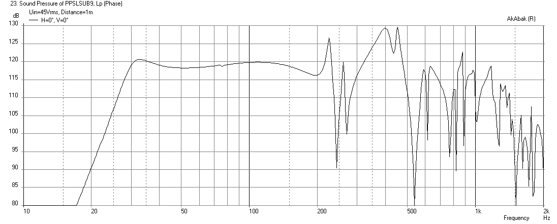
If you corner load this (17in in away from left and right wall, aimed 45deg out), you can get a pretty nice flat response. It has quite a saddle though in open space 2pi. Here is the predicted max SPL with corner loading, 8mm xmax limited, and wired in series for 44 volts, with -24dB/oct HPF at 29Hz to control cone motion below tuning frequency:
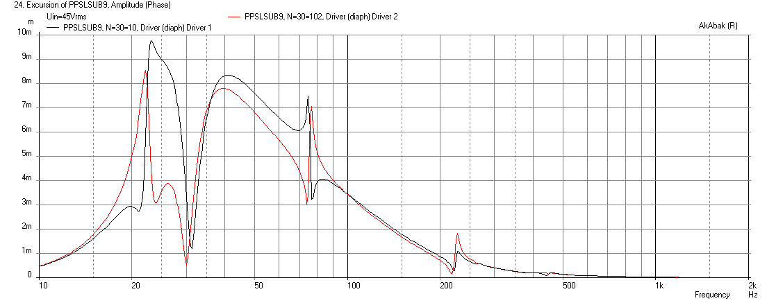
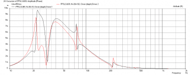
Here is the corresponding cone displacements, and as I suspected, the asymmetry of the chambers causes an asymmetry in the driver cone displacements, especially at lower frequencies. This may negate any of the benefits of balanced anti-hysteresis distortion cancellation we were hoping to get with a push pull geometry:
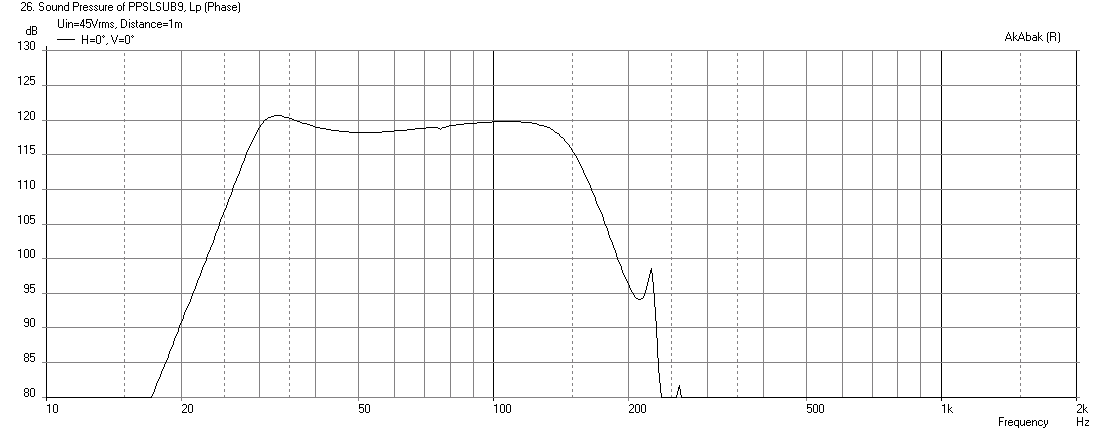
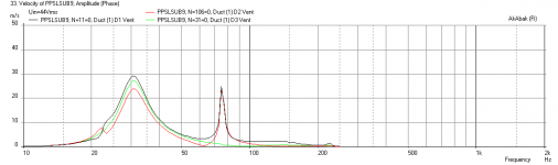
Here is the response with a -48dB/oct 150Hz LPF:
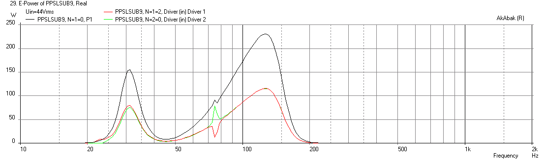
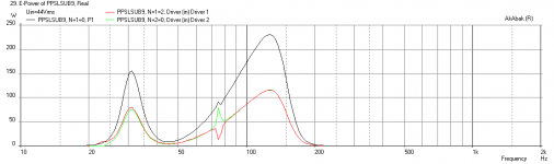
This is the corresponding electrical power input - good match for ratings:
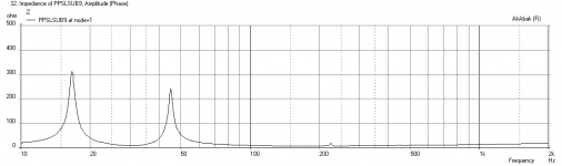
Here is the impedance - kind of high peaks:

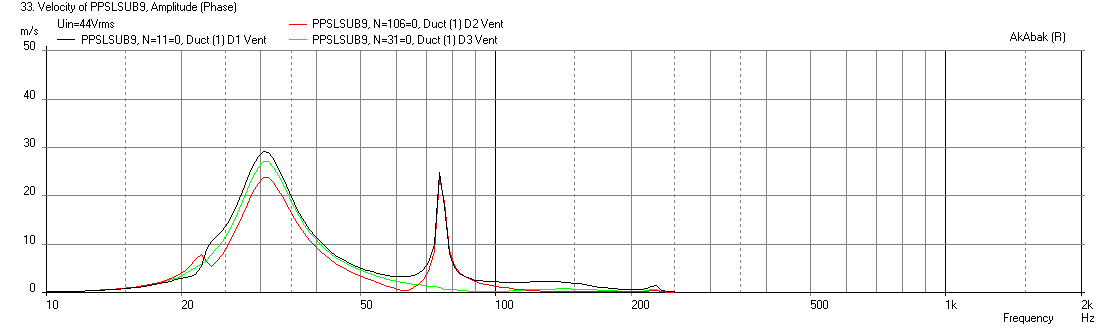
Here is the velocity in the vents (black=short chamber, red=long chamber, green=combined) - at 75Hz, the velocity of the short and long vents appears to be out of phase, which is OK but it is clear that there is asymmetry in the flows:
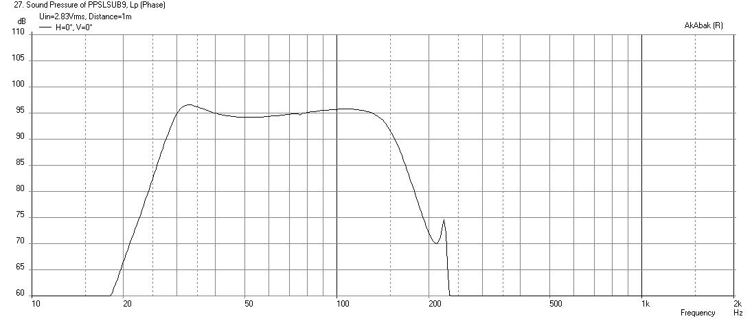
Here is the predicted SPL at 2.83v for reference:
So in summary, I think this can work and probably sound good. Just don't expect any reduction in 2nd order HD due to the PP slot geometry though. It's pretty neat how Akabak is able to immediately show that the effects of an asymmetric dual chamber approach may fare. The cone displacement plot is very complex and indeed shows the interactions between the asymmetric chambers and the drivers via the different length ducts and chambers.
Wait for X's simulation, he might find a slightly different length or cross-section for the ducts advantageous.
Tb46,
I really like your design and how it places the vent in an offset manner. This actually would allow it to be used as a woofer and sub woofer if placed below a full range driver to keep acoustic centers closer together for good integration of the lows and mids/highs.
This was an interesting design from the standpoint of a simulation as I used Waveguide elements to specify the longer chamber (chamber 2) that has an "L" bend, and I used a "Duct" to specify the slightly extended shorter chamber (we will call chamber 1). When you use waveguides and ducts, it allows for TL resonance effects as opposed to a bulk volume element.
If you corner load this (17in in away from left and right wall, aimed 45deg out), you can get a pretty nice flat response. It has quite a saddle though in open space 2pi. Here is the predicted max SPL with corner loading, 8mm xmax limited, and wired in series for 44 volts, with -24dB/oct HPF at 29Hz to control cone motion below tuning frequency:
Here is the corresponding cone displacements, and as I suspected, the asymmetry of the chambers causes an asymmetry in the driver cone displacements, especially at lower frequencies. This may negate any of the benefits of balanced anti-hysteresis distortion cancellation we were hoping to get with a push pull geometry:
Here is the response with a -48dB/oct 150Hz LPF:
This is the corresponding electrical power input - good match for ratings:
Here is the impedance - kind of high peaks:
Here is the velocity in the vents (black=short chamber, red=long chamber, green=combined) - at 75Hz, the velocity of the short and long vents appears to be out of phase, which is OK but it is clear that there is asymmetry in the flows:
Here is the predicted SPL at 2.83v for reference:
So in summary, I think this can work and probably sound good. Just don't expect any reduction in 2nd order HD due to the PP slot geometry though. It's pretty neat how Akabak is able to immediately show that the effects of an asymmetric dual chamber approach may fare. The cone displacement plot is very complex and indeed shows the interactions between the asymmetric chambers and the drivers via the different length ducts and chambers.
Attachments
-
 PPSLBP9-Offset-55-2421-Freq-1m-xmax.png33.5 KB · Views: 338
 -
 PPSLBP9-Offset-55-2421-Freq-1m-2.83v-LPF.png31.7 KB · Views: 343
 -
 PPSLBP9-Offset-55-2421-Velocities-LPF.png14.6 KB · Views: 334
 -
 PPSLBP9-Offset-55-2421-Imped-LPF.png21.3 KB · Views: 341
 -
 PPSLBP9-Offset-55-2421-Electrical-Power-xmax-LPF.png24.9 KB · Views: 333
 -
 PPSLBP9-Offset-55-2421-Freq-1m-xmax-LPF.png29.7 KB · Views: 348
 -
 PPSLBP9-Offset-55-2421-Dsipl-xmax.png33.8 KB · Views: 333
Last edited:
Hi X,
Thanks for the simulation, I'll take a closer look at it tonight. Looks promising. 🙂
Regards,
Thanks for the simulation, I'll take a closer look at it tonight. Looks promising. 🙂
Regards,
Hi lawbiding,
Here is the drawing from Post #177 without the top and bottom boards. Let me know if that fixed it for you.
Regards,
Tb46
I followed all the details that you attach to the drawing when i am doing my layout.. The attach picture will show where I am stuck. I can't get the measurements to match your drawing

Last edited:
Tb46
I followed all the details that you attach to the drawing when i am doing my layout.. The attach picture will show where I am stuck. I can't get the measurements to match your drawing
View attachment 452007
I would not worry about it too much, you can be a little inexact here. The point is to maintain a 1.5in wide channel from the "T" to the throat of the V horn expansion. Move your boards around a bit until that is true. The volume change in the rear chambers and the cone angle affected will be minimal.
I would not worry about it too much, you can be a little inexact here. The point is to maintain a 1.5in wide channel from the "T" to the throat of the V horn expansion. Move your boards around a bit until that is true. The volume change in the rear chambers and the cone angle affected will be minimal.
I will give it a try.
Hi lawbiding,
On a quick look: we are referencing different corners on the individual boards, other wise it is the same. Zoom in on the individual dimensions in the pdfs, and you'll see what I'm saying. Otherwise, I won't have time to look at it till later.
Regards,
On a quick look: we are referencing different corners on the individual boards, other wise it is the same. Zoom in on the individual dimensions in the pdfs, and you'll see what I'm saying. Otherwise, I won't have time to look at it till later.
Regards,
Hi lawbiding,
When I use the corner points that you used I end up with very close to your dimensions, but, because you are using 1/64th (0.015625") and I'm using 3 places decimal they don't look quite the same. Normally I use 4 places decimal, and then convert to the nearest 1/64th for transferring to the wood.
Hope this helps, but if not just ask. 🙂 Maybe we'll get it straightened out yet.
Regards,
Attachments
Lawbiding,
It looks like the predicted performance is good enough for you to proceed? Did you buy the drivers yet? It will be really interesting to see how this works out.
It looks like the predicted performance is good enough for you to proceed? Did you buy the drivers yet? It will be really interesting to see how this works out.
Lawbiding,
It looks like the predicted performance is good enough for you to proceed? Did you buy the drivers yet? It will be really interesting to see how this works out.[/QUOTE
I order a pair of 8" drivers mcm electronics and a single gto1214d from sonic electronix for my girl car. They should be here by Friday.
To Post #185
Hi xrk971,
To Post #185:
First thanks for your effort, I'm particularly interested in this one as I'm hoping to build two helper subs/stands for myself. I have some old 2-ways that need a stand, and some help below. Also,I want to find something to build w/ the MCM 55-2421 around the PPSL_SV design. It will be a little bit different, but all the data from here should apply.
Looking @ the SPL graph:
How about using a 2nd order HPF to cut down the lower peak (or maybe a little more for a slightly downwards slanting response), and letting the "room gain" help in that area and below? For the upper end I will be cutting everything above 80-100Hz w/ a 4th order BW LPF. So this looks fine.
Cone displacement:
I'm surprised about the cone behaviour of the red line around 22/23Hz, and both lines @ 75Hz.
I looked @ the drawing from a TH viepoint, and the front chamber has path length(s) right around the 75Hz point. So that may cause the 75Hz problem.
Thanks again.
Regards,
Attachments
Hi xrk971,
To Post #185:
First thanks for your effort, I'm particularly interested in this one as I'm hoping to build two helper subs/stands for myself. I have some old 2-ways that need a stand, and some help below. Also,I want to find something to build w/ the MCM 55-2421 around the PPSL_SV design. It will be a little bit different, but all the data from here should apply.
Looking @ the SPL graph:
How about using a 2nd order HPF to cut down the lower peak (or maybe a little more for a slightly downwards slanting response), and letting the "room gain" help in that area and below? For the upper end I will be cutting everything above 80-100Hz w/ a 4th order BW LPF. So this looks fine.
Cone displacement:
I'm surprised about the cone behaviour of the red line around 22/23Hz, and both lines @ 75Hz.
I looked @ the drawing from a TH viepoint, and the front chamber has path length(s) right around the 75Hz point. So that may cause the 75Hz problem.
Thanks again.
Regards,
Tb46
Please see attach picture.

Hi lawbiding,
That little piece was necessary to get the duct length for both chambers to the same length of 23".
See the bottom right hand of the dimensions drawing in Post #177 for the alternate/simplified version. When you leave the little piece out, the right hand chamber duct gets to be a little longer, and the same amount will have to be added to the left hand duct.
I think it will work either way.
Regards,
The 24Hz and 75Hz are pipe resonance frequencies or beat notes thereof. That is what you get when you put two oscillators with different natural resonance frequencies into one system. There may be a way around this by making both the front and rear/lower chambers one big one rather than two separate ones. Then have just one 1.5in x 23in long vent feeding the SV. This will require some sort of flow paths between the front and back chambers - so the slot vent will have a larger box around it rather than go to the side walls. This will make a more squat shape, although you can play with depth to get height back up to 25in.
Hi lawbiding,
When I use the corner points that you used I end up with very close to your dimensions, but, because you are using 1/64th (0.015625") and I'm using 3 places decimal they don't look quite the same. Normally I use 4 places decimal, and then convert to the nearest 1/64th for transferring to the wood.
Hope this helps, but if not just ask. 🙂 Maybe we'll get it straightened out yet.
Regards,
Tb46
Please see attach picture.
I give it try,hope I am close. lol

Hi lawbiding,
I looked at the picture, and there are some pretty big differences between the dimensions in you drawing and the dimensions in mine (i.e.: 1/8") that should not be there, but, if you go with the dimensions in my drawing you should not have any problems. Draw the oulines on one of the side boards, and take your final cut dimensions from there. That should do it.
Earlier you asked about the difference between this design, and a standard bass-reflex. The difference is mainly in the location of the vent, so you could close of the slot-vent in the back of the plenum, and remove the current slot venting. You would be using the complete internal chamber, and then add a standard bass-reflex vent/duct to the box, e.g.: 4"Dia. x 23" long. I haven't played w/ the simulations in a while, but the outcome should be similar. You would still want to use the PPSL plenum for distortion cancellation.
Regards,
- Home
- Loudspeakers
- Subwoofers
- PP Slot Loaded Sub with Alpine SWR 12D2