Current roughly determines wire mass, which is the key to thermal inertia, the issue at hand here.
not exactly because thoriated fillaments run at 2700K and oxide ones at 900K. energy loss due to radiation is different...Not to mention the oxide coating increases thermal mass(purely speculative)
Last edited:
A properly sized thermistor in series with AC filament will make a gentle start-up.
True, but on a 2K amplifier 20-30 bucks for parts will give you zero hum
Either design a very good DC supply for DHT filaments . . .
Or . . .
Just fall back to using AC filaments.
I gave that a shot, and got under 300uV on my friends 6A3/6B4G. but the tread got derailed by bickering. It has all the bells and whisles. and i have the board files online for free.
Heres an RV218 amp he built with them. Hes running one of my tube reg designs to give .2mV of ripple
Attachments
Decades ago I should have taken photographs of DHT amplifiers with AC filaments.
We used an HP 3585 spectrum analyzer.
You just look at the 1kHz test sine wave, and you see 880Hz and 1120Hz sidebands on the test tone. This was with tubes like 300B or 2A3.
And the second harmonic (distortion of 1 kHz) had 880 and 1120 sidebands too.
And the 3rd harmonic (distortion of 1kHz) had 880 and 1120Hz sidebands too.
Oh, did I say HP 3585? It worked real good.
We did not have a Tektronix 7L5 where we were located to use for that measurement.
. . . jhstewart9, I am willing to admit this.
Last edited:
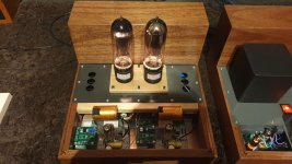
V4lve lover,
Your friend has a nice looking amplifier.
Do not look for hum (50/100 or 60/120 depending on the power mains).
That is important.
But, intermodulation of 2X power mains frequency on each music tone is more important . . .
Build 2 DHT power amplifiers:
Put a pure 1kHz tone into the DC filament powered amplifier, and measure with a spectrum analyzer. No upper and no lower sidebands on 1kHz.
Put a pure 1kHz tone into the AC filament powered amplifier, and measure with a spectrum analyzer. There will be upper and lower sidebands on 1kHz. (sideband equal to 2X power mains frequency).
What tells you that it is not mainly a thermal effect, is that it changes versus the signal level. That is the nature of intermodulation.
With thermal sidebands, the level of the upper and lower sidebands would remain more constant, even when the signal level changes.
Regardless of the cause, putting 2X power line mains frequency upper and lower sidebands on every music note is not a good thing, is it?
Just my opinion.
Last edited:
I know what you mean. thank you i will pass on the compliment.
PS
1206 ferrite beads are golden theres not a switching noise you cant take to the woodshed with 10 cents of compact SMD beads. One of the things s i still want to do is a 2A buck regulator that you can feed 10-60VDC with a linear post regulator. and an optocoupler over the linear reg to get the buck to track the linear reg. I have all-ready budgeted a whopping 6 cents for beads so i can get it as quet as a normal linear PSU.
Dont believe me: take it from the late Analog titan https://www.analog.com/media/en/technical-documentation/application-notes/an101f.pdf
Last edited:
Thermal inertia is determined by mass alone, not by coatings, etc. Thick filament, more inertia; thin filament, less.
It is not about cost, it is about whether regulators provide enough improvement to bother with them. If I have 12 tubes in my amp and need 12 regulators to reduce IMD from 0.1% to 0.05%, I am not sure I want to go that way.
It is not about cost, it is about whether regulators provide enough improvement to bother with them. If I have 12 tubes in my amp and need 12 regulators to reduce IMD from 0.1% to 0.05%, I am not sure I want to go that way.
I have no financial interest in my design anymore. And my honest answer is: maybye it depends on the amp. I think that If you order everything yourself, you will be looking at 240-300US for 12 tubes.
The flipside is that if im correct by assuming tube life increases, this could save you long therm. And time=money if your 12 tube amp takes half a day for the heaters nicely twisted and laid out. wheras DC you can just make looms and tie rip them together, there may be savings there
The flipside is that if im correct by assuming tube life increases, this could save you long therm. And time=money if your 12 tube amp takes half a day for the heaters nicely twisted and laid out. wheras DC you can just make looms and tie rip them together, there may be savings there
Some people are never satisfied, the GM70 version i cannot share.. The 2.5A capable one however is available for free as a board design that you can order from China.
I have a couple of boards in my “free gerber thread” including HV cap boards and time delay biard with 555 and relay.. May be worth investing some dough in cheap PCB”s from China.
I have a couple of boards in my “free gerber thread” including HV cap boards and time delay biard with 555 and relay.. May be worth investing some dough in cheap PCB”s from China.
Last edited:
I'm not really believing Stephie's theory of causation. Just can't believe that the space charge is that variable with whatever tiny temperature variations occur locally on a filament of any description.
But she may be right - how could we tease this effect out from the voltage effect, by actual test?
YOS,
Chris
But she may be right - how could we tease this effect out from the voltage effect, by actual test?
YOS,
Chris
I also thought so. The space charge should provide ample buffering for minuscule emission fluctuations. And tubes are running at less than their rated cathode current. But Steve provides this IMD table...
In AC-powered amplifier, it is very difficult to figure the real cause of AC-derived intermodulation. There could be many causes other than thermal modulation of the filament.
In AC-powered amplifier, it is very difficult to figure the real cause of AC-derived intermodulation. There could be many causes other than thermal modulation of the filament.
Last edited:
I thing simply the inductance of the heater is also playing a part. This is the reason i dont like HF heating... you can measure up to the glass to metal seal, anything beyond that is impossible in Situ..
Few nH should be like straigjt wire for the frequencies in question. But who knows, cannot discount anything.
1. Hum with no signal present:
With an AC powered DHT filament, residual hum is there even if there is no signal (fundamental of the power mains frequency, 60Hz for example). Suppose it is 500uV of 60Hz.
When a moderate level signal is applied, the residual hum is still there, it is still 500uV of 60Hz.
With no signal, there is no 880Hz and is no 1120Hz present.
Again, with an AC powered DHT filament, with no signal present, if there is 500uV of 120 Hz hum, perhaps it is caused by one or more filament wires that are closer to one side of the steel plate than the other side of the plate. In that case, the 120 alternation current causes the wire to be attracted more to the closer side of the plate. The motion of the filament wire causes modulation of the plate current.
The filament moves closer to that side of the grid, and moves closer to the closer side of the plate. There is no 880Hz, and no 1120Hz when there is no 1kHz signal.
2. With signal applied:
Apply a 1kHz tone, and now there are 880Hz and 1120Hz tones present.
I say that is either AM modulation, or 2nd order Intermodulation distortion (you pick which one you want to call it).
If you use an AM detector to measure that amplifiers output signal of the AC filament powered DHT amp, you will get 120Hz modulation signal out.
But, if you use an FM detector on that same amplifier output signal of the AC powered DHT amp, that has 880, 1000, and 1120Hz signals, there will be no 120Hz signal detected (it is not FM modulation).
The phase of AM sidebands versus FM sidebands are different; so it can be proven if the signal is AM or FM, merely by using both an AM detector, and an FM detector, and finding which has a 120Hz output.
A digital demodulator, such as in Tektronix spectrum analyzers has both AM and FM detectors.
I am sure there are other brands of spectrum analyzers that can do the same.
Last edited:
If you really want to be splitting hairs, its a network or resistance parasitic inductance, all encased in a vacuum with vastly different potentials and some minor capacitative coupling inside.
You may also be interested in the Barkhausen effect, you can build an oscillator out of tubes that have perfectly cylindrical anodes.
You may also be interested in the Barkhausen effect, you can build an oscillator out of tubes that have perfectly cylindrical anodes.
It'd be hard for most of us to even measure that small an inductance, and significant EM field at 50 or 60 Hz?
But can easily agree that ultrasonic heating is a wrong path - the IM's still there and the complication is silly hard. But to each...
YOS,
Chris
But can easily agree that ultrasonic heating is a wrong path - the IM's still there and the complication is silly hard. But to each...
YOS,
Chris
v4lve lover,
There are many RF tubes with perfectly circular plates, perfectly circular grids, and perfectly circular cathodes.
You do not need to use the Barkhausen effect to build an oscillator using those tubes.
4X150A, circular planar 416A, and many others.
There are many RF tubes with perfectly circular plates, perfectly circular grids, and perfectly circular cathodes.
You do not need to use the Barkhausen effect to build an oscillator using those tubes.
4X150A, circular planar 416A, and many others.
Last edited:
- Home
- Amplifiers
- Tubes / Valves
- PP DHT output stage, is DC heater necessary?