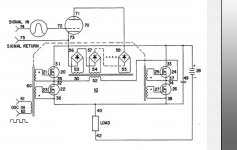
These are diode bridges, each bridge can handle about 75V @500Khz, This can not be done with standard diodes so i need fast switching diodes. As the voltages here can be several hundreds i need to stack the bridges.
Attachments

Last edited:
UF4007 is fast enough to do so i think.
You should see this flyback, https://www.tme.eu/nl/details/ti-ef25-1068/pcb-transformatoren/feryster/
You should see this flyback, https://www.tme.eu/nl/details/ti-ef25-1068/pcb-transformatoren/feryster/
There's plenty of single fast recovery diodes that do just that for SMPS etc. Love the approach.
@Lampie519, you sent me that PDF a year or two ago, tried to understand it but I still don't fully grasp what is going on. But maybe I try to understand it too well 🙂
75uS reverse recovery time against 8nS of the 1n4148
BAV21 then? Sorry i was trying to be smart
Yes, these are fine, i could half the amount of diodes, but the 1n4148 are cheap so i do not care.
I've not had the best day so at the risk of letting out a brain fart like V4lvelover did, Do you have to add all those 8ns recovery times up or does it not work like that?
@Gideon,
its an H-Bridge that creates a square wave switching the magnetic field on these transformers (step up), But the audio signal is not . By doing so the tube can be fed with a dc voltage and the result on the output would also be a true DC offset (not possible with a "standard" transformer).
its an H-Bridge that creates a square wave switching the magnetic field on these transformers (step up), But the audio signal is not . By doing so the tube can be fed with a dc voltage and the result on the output would also be a true DC offset (not possible with a "standard" transformer).
Attachments
Last edited:
Lampie, thanks for posting the link to Steve Bench's article. I've read it before, but it was such a long time ago that I have thoroughly forgotten. Was good to refresh my memory and to correct some misunderstanding that I used to have.
From Steve's account, there are two sources of filament hum: 1) slight asymmetry and 2) thermal inertia of filament. The 1) can be reduced to acceptable level by hum bucking pot and compensation for mains frequency harmonics. The 2) is more troublesome because it cannot be compensated, and because instantaneous changes in filament temperature, occurring at 2x mains frequency, cause changes in tube's transconductance, which in turn causes intermodulation.
Thermal modulation should affect power stage more than voltage amplification stage. In fact, a voltage amplification stage loaded with a CCS should not be affected at all, since it's gain is equal to amplification factor and does not depend on Gm.
Thermal modulation should decrease as heat inertia of filament increases. Heat inertia can be determined by filament current: the higher the current, the more inertia. Here are filament currents of some tubes:
1J24B: 0.013 A
30: 0.05A
01A, 71A: 0.25 A
26, 6A3: 1.0 A
10Y, 801A: 1.25 A
45: 1.5 A
46, 47: 1.75 A
1624: 2.0 A
2A3: 2.5 A
GM70: 3.0 A
211, 845, 8042: 3.2 A
The tubes on top of the list, down to 71A, were not intended for AC heating. The ones at the bottom should be much more forgiving in this regard. So, it would be reasonable to AC heat a GM70 output stage, and maybe not so a 6A3 one. Please note that heater voltage doesn't matter here, what matters is heater current.
AC heat modulation should increase as plate current increases. At low plate currents, the effect should be less pronounced or even absent because cathode will have excess emission capacity.
Now, rip me apart with critique.
DHT + AC heaters = 2X line frequency intermodulation (upper and lower sidebands)
on each and every musical note.
The percentage of intermodulation depends on the tube, and the signal level.
1. Extremely low signal levels is one thing.
2. Large signal levels at or near to 0V grid to filament voltage is more serious.
3. At the point of drawing grid current, the intermodulation is paramount.
Just one man's opinion.
One more argument against DC heating is necessity of using solid state rectification. For those who believe in the advantages of vacuum rectifiers, that could be an important concern.
I personally hold the opinion that there is nothing wrong with solid state, however if you absolutely have to use a tube. back in the day they made tungar rectifiers for low voltage high current.
vacuum rectifiers have no advantages its better to use a time delay and a tube regulated PSU. best of both worlds? because the tube still gives slow warm up.
vacuum rectifiers have no advantages its better to use a time delay and a tube regulated PSU. best of both worlds? because the tube still gives slow warm up.
Either design a very good DC supply for DHT filaments . . .
Or . . .
Just fall back to using AC filaments.
Or . . .
Just fall back to using AC filaments.
vacuum rectifiers have no advantages
SS rectifiers make noise because they have abrupt current cutoff at their non-zero forward voltage. This noise can be reduced to some extent by snubbing, but cannot be completely eliminated. Tube rectifiers don't have this problem.
Tungar? You kidding me, right?
Lampie, thanks for posting the link to Steve Bench's article. I've read it before, but it was such a long time ago that I have thoroughly forgotten. Was good to refresh my memory and to correct some misunderstanding that I used to have.
From Steve's account, there are two sources of filament hum: 1) slight asymmetry and 2) thermal inertia of filament. The 1) can be reduced to acceptable level by hum bucking pot and compensation for mains frequency harmonics. The 2) is more troublesome because it cannot be compensated, and because instantaneous changes in filament temperature, occurring at 2x mains frequency, cause changes in tube's transconductance, which in turn causes intermodulation.
Thermal modulation should affect power stage more than voltage amplification stage. In fact, a voltage amplification stage loaded with a CCS should not be affected at all, since it's gain is equal to amplification factor and does not depend on Gm.
Thermal modulation should decrease as heat inertia of filament increases. Heat inertia can be determined by filament current: the higher the current, the more inertia. Here are filament currents of some tubes:
1J24B: 0.013 A
30: 0.05A
01A, 71A: 0.25 A
26, 6A3: 1.0 A
10Y, 801A: 1.25 A
45: 1.5 A
46, 47: 1.75 A
1624: 2.0 A
2A3: 2.5 A
GM70: 3.0 A
211, 845, 8042: 3.2 A
The tubes on top of the list, down to 71A, were not intended for AC heating. The ones at the bottom should be much more forgiving in this regard. So, it would be reasonable to AC heat a GM70 output stage, and maybe not so a 6A3 one. Please note that heater voltage doesn't matter here, what matters is heater current.
AC heat modulation should increase as plate current increases. At low plate currents, the effect should be less pronounced or even absent because cathode will have excess emission capacity.
Now, rip me apart with critique.
Thermal inertia is not that simple, a heater is far more complex than just the voltage and current products would suggest. For this to be true all heaters would have to be made from the same material with the same mass/power. which us incorrect. The amount of power you need is dependable on at least half a dozen factors.
Emmision coatings for oxide heaters come in more than a dozen formula, for different applications. This has to do with the actual engineering behind building tubes. and these coatings are applied in varying thicknesses across different types and brands.
I think there was a RCA book that covered the fundamentals of vacuum tube engineering.
moreover, Gain is a product of internal impedance in parallel with the Zout of the current source multiplied by the mutual conductance. This is purely technical hair splitting as GM and RI are almost inversely proportional meaning that if one decreases due to aging the other will increase.
Intermodulation is a real thing, but not as big as its made out to be. And the only reason why you would want to use DC is that you can have controlled warm up characteristics for the fillaments. The fact that DC is more forgiving and causes less hum/ high current AC wires running through your chassis is just the cherry on top.
if you want to keep it simple and dont want to muck about with current sources. this special ED class case has just the thing for you: L200 regulator. This simple part can be programmed with one resistor to limit the current during startup
Current roughly determines wire mass, which is the key to thermal inertia, the issue at hand here.
SS rectifiers make noise because they have abrupt current cutoff at their non-zero forward voltage. This noise can be reduced to some extent by snubbing, but cannot be completely eliminated. Tube rectifiers don't have this problem.
Tungar? You kidding me, right?
Show me oscilloscope screenshots and give me a 10 cent budget for improvements.
- Home
- Amplifiers
- Tubes / Valves
- PP DHT output stage, is DC heater necessary?