That's a nice thing to have.
Do you listen to that original RCA amp?
What speakers do you use it with?
How do you like the amp?
Do you listen to that original RCA amp?
What speakers do you use it with?
How do you like the amp?
rongon,
Yes, if the driver cathode currents are equal, then just go back to tying the two 6AU6 screens together, and use, or do not use, a bypass cap from the screens to ground. To use, or not to use, a bypass cap depends on the level of distortion (and the relative strength of the 2nd order and 3rd order distortion), although they will be similar, because of the output plate to driver cathode negative feedback.
Output stage plate negative feedback, and global negative feedback hides a multitude of errors;
However, lamination saturation can not be hidden, it will be made worse.
If you can, it might be a good idea to test the 2nd and 3rd order Intermodulation distortion. IMD often follows HD, so only do this if you are curious.
If you have a oscilloscope FFT, you may be able to see the distortion sidebands of the IMD.
I use the Denon Audio Technical CD, it has two sets of test tone pairs, one set for 2nd order IMD, and one set for 3rd order IMD.
If you look at the scope FFT when the amplifier is clipping, you will not like the harmonic distortion test, and you will not like the Intermodulation test.
They will look ugly.
That is why I make sure to turn my volume down to prevent clipping.
Some of my amplifier's low gain prevents clipping, at DAC Full Scale, even if the passive volume control is turned all the way clockwise.
So many schematics in this thread.
I think I saw one that had no cap to the output of L1.
I can not find any schematic that does not have the bypass cap to ground at L1 (except the early truncated schematics that did not even show L1.
$0.03

I wish I knew how to simulate IMD. I'll look into that.
I look at the virtual scope FFT in LTspice all the time, to gauge what clipping behavior looks like. I want to see the least amount of upper harmonics possible, as well as no resonances at ultrasonic frequencies.
My apologies for all the chopped up schematics. I'm trying to show what I'm looking at, at each step along the way. I'll stop posting schematics until something major is resolved.
___________________________________________
The more I look into this circuit, the more it seems those RCA engineers really knew what they were doing. If I swap the driver tubes to 6EJ7 and bias them so that they each draw 2mA plate current and 1mA screen current, the THD goes up to 0.015%, but significantly, that is all H3, as the H2 is cancelled by balanced CMR. For some reason, that current-starved 6AU6 scheme results in lower H3 to the speaker load. Now this is all in an idealized environment and in simulation only. But, I've found that if I simulate a circuit very carefully before I build, the final result will be pretty close to the sim. That's pretty cool, if you ask me.
So far the best I can do is:
Again in simulation, the output impedance (Zout) for 1kHz signal at the 8 ohm speaker tap appears to be less than 1 ohm, something like 0.3 ohm. Too good to be true? (I measured it in simulation by reducing the value of the load resistor at the 8 ohm tap until the voltage across the load was -6dB down from what it was across 8 ohms.)
Whatever input-phase splitter I choose will have to deliver a clean 12V peak signal per phase to preserve that low distortion. It looks like all the THD comes from the original 12AU7 circuit. Does this current-starved pentode diff stage w/ feedback from the output tube plates present a difficult load to the previous stage (phase splitter)? Does the phase splitter need to have a really low Zout and be able to sink a fair amount of current into its load?
I found out that the original SP-10 used a Stancor A-3311 output transformer. In the Stancor catalog from 1983, it's shown as rated for 25 watts output, but its max plate current is 70mA per side (each output tube). Frequency response is rated at 60Hz to 20kHz. I think that 25 watt rating is inflated a bit. If the transformer was rated for 30Hz output, the max power out would probably be 15W or maybe 10W.
I have a pair of Transcendar 8k:4 ohm 35W OPTs I got just before the nice guy who wound those closed down the business. They don't have UL screen taps, so this might be a good project for those.
On the other hand, it might be that this circuit does better with the higher 10k ohm plate-plate load, to reduce current demands at low frequencies, etc. I'll look into that...
I look at the virtual scope FFT in LTspice all the time, to gauge what clipping behavior looks like. I want to see the least amount of upper harmonics possible, as well as no resonances at ultrasonic frequencies.
My apologies for all the chopped up schematics. I'm trying to show what I'm looking at, at each step along the way. I'll stop posting schematics until something major is resolved.
___________________________________________
The more I look into this circuit, the more it seems those RCA engineers really knew what they were doing. If I swap the driver tubes to 6EJ7 and bias them so that they each draw 2mA plate current and 1mA screen current, the THD goes up to 0.015%, but significantly, that is all H3, as the H2 is cancelled by balanced CMR. For some reason, that current-starved 6AU6 scheme results in lower H3 to the speaker load. Now this is all in an idealized environment and in simulation only. But, I've found that if I simulate a circuit very carefully before I build, the final result will be pretty close to the sim. That's pretty cool, if you ask me.
So far the best I can do is:
- Replace 6AU6s with 6CB6 (reduces THD by half, plate current goes from 325uA to 470uA).
- Replace 6V6s with 6JC5 (reduces H3). Here's something that should make @6A3sUMMER happy: The 6JC5 data sheet says its maximum allowable grid leak resistance for cathode bias operation is 2.2Mohm. I put 1Mohm in the simulation. Thanks again @smoking-amp !
- With 3.5V peak signal into the driver stage and output stage only, closed loop, the result is that the THD for 1kHz sine wave at 1W out into 8 ohms is 0.002% (!!!).
Again in simulation, the output impedance (Zout) for 1kHz signal at the 8 ohm speaker tap appears to be less than 1 ohm, something like 0.3 ohm. Too good to be true? (I measured it in simulation by reducing the value of the load resistor at the 8 ohm tap until the voltage across the load was -6dB down from what it was across 8 ohms.)
Whatever input-phase splitter I choose will have to deliver a clean 12V peak signal per phase to preserve that low distortion. It looks like all the THD comes from the original 12AU7 circuit. Does this current-starved pentode diff stage w/ feedback from the output tube plates present a difficult load to the previous stage (phase splitter)? Does the phase splitter need to have a really low Zout and be able to sink a fair amount of current into its load?
I found out that the original SP-10 used a Stancor A-3311 output transformer. In the Stancor catalog from 1983, it's shown as rated for 25 watts output, but its max plate current is 70mA per side (each output tube). Frequency response is rated at 60Hz to 20kHz. I think that 25 watt rating is inflated a bit. If the transformer was rated for 30Hz output, the max power out would probably be 15W or maybe 10W.
I have a pair of Transcendar 8k:4 ohm 35W OPTs I got just before the nice guy who wound those closed down the business. They don't have UL screen taps, so this might be a good project for those.
On the other hand, it might be that this circuit does better with the higher 10k ohm plate-plate load, to reduce current demands at low frequencies, etc. I'll look into that...
Last edited:
Update --
I was running all these simulations with a model of a Hammond 1608 OPT, 8k ohms to 8 ohms.
I just updated that to a model of a Hammond 1609 OPT, 10k ohms to 8 ohms.
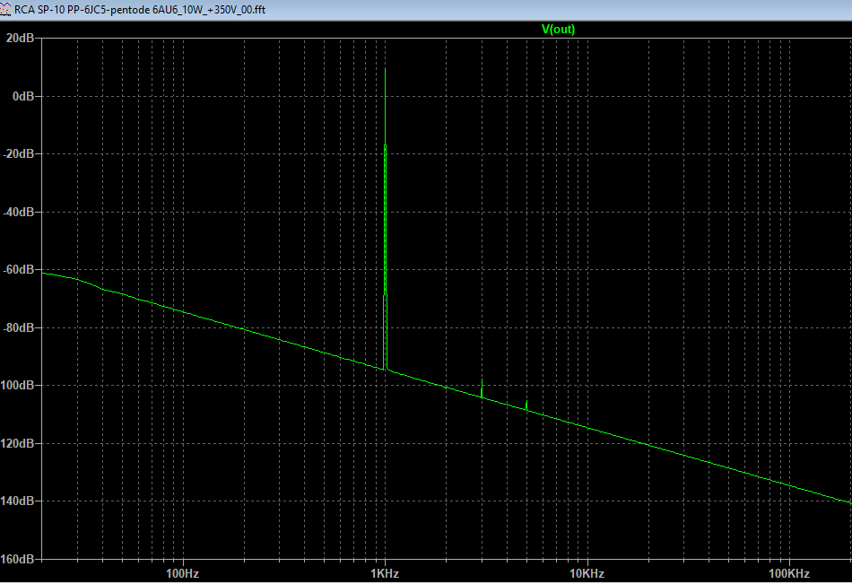
That reduced H3 even more. Now it's basically non-existent at 1W out into 8 ohms. The FFT looks like the output from an op-amp.
This is probably too good to be true, and is sure to be spoiled by psu noise and whatever voltage amp/phase splitter stage comes before the PP driver stage, but it sure does look good so far.
I was running all these simulations with a model of a Hammond 1608 OPT, 8k ohms to 8 ohms.
I just updated that to a model of a Hammond 1609 OPT, 10k ohms to 8 ohms.
That reduced H3 even more. Now it's basically non-existent at 1W out into 8 ohms. The FFT looks like the output from an op-amp.
This is probably too good to be true, and is sure to be spoiled by psu noise and whatever voltage amp/phase splitter stage comes before the PP driver stage, but it sure does look good so far.
Attachments
rongon,
1. If LTspice can generate 2 sine waves, and apply them to the amplifier input, then you can see the Intermodulation Distortion Products on your simulation FFT.
My Denon Audio Technical CD: THE two sets if 2 tone IMD test sine waves:
2nd Order Intermodulation tones: 250Hz and 8020Hz. The 250Hz tone is 4 times more voltage than the 8020Hz tone (+12 dB more amplitude at 250Hz than at 8020Hz).
You will see the 2nd order intermodulation distortion, it appears as 250Hz upper and lower sidebands on the 8020Hz tone (at 7770Hz, and 8270Hz).
I think 4:1 voltage amplitude is per SMPTE standards (Society of Motion Picture and Television Engineers)
Where are jhstewart9, and so many others who can chime in?
3rd Order Intermodulation tones: 11kHz and 12kHz. The voltage the two tones are Equal voltage (different than the standard 2nd Order test @ 4:1 voltage).
You will see the 3rd order intermodulation distortion, it appears as 10kHz lower sideband, and 13kHz upper sideband.
Note, because the difference of 11kHz and 12kHz is 1kHz, guess what . . . you will also see the 2nd order IMD product at 1kHz.
I hope this helps you and others who are wondering.
Please let us know if you are able to do this in LTspice.
2. Yes, those RCA Engineers really knew what they were doing in the old days.
And so did WE Engineers, and so many other vacuum tube manufacturers who had to use, or tell others how to use, their vacuum tubes.
$0.03
Thanks for the ideas. That does help.
I think I can get two sine waves playing by defining two AC voltage generators and put them in series, swinging the grid of the input stage. I can define what frequency and amplitude I want from each. So yes, I think this can be easily done.
Question about the IMD measurements:
In other news, I'm trying to decide on what OPT to use. So far, I've found that:
I think I can get two sine waves playing by defining two AC voltage generators and put them in series, swinging the grid of the input stage. I can define what frequency and amplitude I want from each. So yes, I think this can be easily done.
Question about the IMD measurements:
- How do I choose signal levels? Do I adjust them to get a certain output into the speaker load, e.g., 1W?
- It might be difficult to figure out the command to run a transient analysis on two sine waves at the same time.
In other news, I'm trying to decide on what OPT to use. So far, I've found that:
- Using an OPT with 10k plate-plate primary impedance yields the lowest THD, especially H3. THD is 0,028% at 1W out (1kHz). H2 -71.5dB but H3 is way down below -100dB. However, that comes at the price of much lower max power output. It looks like I will get no more than 8.5W rms per channel at 1% THD (1kHz).
- Using an OPT with 6.6k primary means much higher H3, while H2 remains roughly the same. THD is 0.023% at 1W out (1kHz). H2 -72.5dB and H3 -74.5dB. Max power out at 1% THD is 21W. That's more than double the power, which means it would actually make an audible difference. Hmmm....
I like your idea of putting the two sine waves in series.
Suppose that a single sine wave of 100mV rms gives 1 Watt out.
You know what your amplifier gain is, so you know how many millivolts rms gives you 1 watt out. (1 Watt into 8 Ohms is 2.828Vrms, or 4V peak, 8V peak to peak)
Again, suppose 100mVrms gives you 1 Watt out. 100mVrms is 141.4millivolts peak
So, set the 11kHz sine wave to 50millivolts rms, and set the 12kHz sine wave to 50millivolts rms. When the 2 sine waves are briefly in phase, there will be
+141mV peak positive, and in the opposite direction -141mV peak negative. The is the same as a single sine wave of 100mVrms.
The point is to make the sum of the two tones to be the same as the peak voltage you would use for a single sine wave.
Your output at 1% THD is 8.5 Watts.
You might set a single sine wave for 5 Watts out, and then set the sum of the 2 tones to be the same amplitude as the single sine wave.
I think the FFT function will show the original 2 tones, and the upper and lower sidebands that are at 10kHz and 13kHz.
As long as you can find the relative dBc from the tone to its upper and lower sideband, you can calculate the percent distortion.
I do not know if the FFT will calculate the distortion % or not.
For the 2nd order IMD, set the 250Hz tone to 80mVrms, and the 8020 tone to 20mV rms (that has the peak equivilent of the single tone @ 100mVrms).
That example shows the proportions, but you will need more or less voltage to make the tubes swing as far as 1 Watt, 5 Watts, or whatever Wattage you select.
This is all about setting the sum of the two tone peak voltages the same as the single sine wave peak voltage.
Just set to rms volts or to peak volts, use the same for the single sine wave, as you do for the sum of the two IMD tones.
I am finding it hard to make it clear, I hope you can figure it out.
I have contemplated an amp like the SP20/10 since hearing one two decades ago. Best commercial amp ever...and of course I wanted to try tweaking it. For OPT iron, the Heyboer-sourced S265Q is an obvious choice for single pair PP. 5-6k for the PPP, and I have some O-Netics for that.
I figured a solid LTP input stage. Likely a 6H6Pi running as hot as reasonable plate loads would allow given B+ limitations. 6AU6 are pretty fine in this app, but decidedly( imo ) need to run higher current to be 'proper'.
The amp is likely going to shake out as a 6L6GC amp built with those O-Netics opt's, class A pentode so as to allow me reasonable B+ for the front end. 6H6Pi LTP input stage and almost certainly a 9-pin pentode for the driver. 6EJ7 comes to mind... 🙂
Douglas
Which amp did you hear, the SP10 or the SP20? I'm glad to hear that you thought it was good. "Best commercial amp ever"? Wow!. I guess I can throw the whole stash of power supply parts at this project. Go the deeeee-lux route.
I'd be very interested to see how you would get more current running through the 6AU6s while maintaining the same amount of NFB from output plates to driver cathodes.
I went crazy yesterday, experimenting in LTspice trying different tube types and OPTs, sticking to the same (current starved) driver circuit. So far I have:
I don't have any 10k OPTs. I used to have a pair of UTC LS-63. Those had 10k and 6k primary windings, rated for 20W. I sold them for a tidy profit years ago, but now I wish I'd kept them. They'd have been perfect for this project, and they were beautiful. Sounded nice too. Oh well...
I've been finding that the higher impedance OPT primaries yield lower H3 but reduced power. Lower the primary impedance and you get more power along with higher levels of H3. THD is nice and low in all cases, but the balance of H3 to H2 changes. Would that make a difference? I don't know.
I'm really excited about this project. I need 20W per channel to drive contemporary bookshelf speakers. I don't need to go loud, but I do need the low Zout and some current to drive a 4 ohm speaker load. So it's encouraging to hear that the original SP-10 (or SP-20) sounds good in real life. 👍
I'd be very interested to see how you would get more current running through the 6AU6s while maintaining the same amount of NFB from output plates to driver cathodes.
I went crazy yesterday, experimenting in LTspice trying different tube types and OPTs, sticking to the same (current starved) driver circuit. So far I have:
- Dual mono or monoblock construction, because the B+ will be +330V from a pair of 500VCT 150mA power transformers I got from Fair Radio way, way long ago. They cost $6 each! 🙂
- The input voltage amp and split load phase inverter will be 6SN7 instead of 12AU7. Also, re-bias that so that both triodes draw 3mA plate current. THD is reduced a lot in those stages.
- Swap in 6CB6 pentodes in place of the 6AU6s. Ip increases to 470µA, Ig2 increases to 270µA. Roughly 2X the gm. Still current starved, though.
- Swap in 6JC5 beam pentodes in place of the 6V6s, thanks to a hot tip from smoking-amp. It looks like I should get 18W from a pair of those.
I don't have any 10k OPTs. I used to have a pair of UTC LS-63. Those had 10k and 6k primary windings, rated for 20W. I sold them for a tidy profit years ago, but now I wish I'd kept them. They'd have been perfect for this project, and they were beautiful. Sounded nice too. Oh well...
I've been finding that the higher impedance OPT primaries yield lower H3 but reduced power. Lower the primary impedance and you get more power along with higher levels of H3. THD is nice and low in all cases, but the balance of H3 to H2 changes. Would that make a difference? I don't know.
I'm really excited about this project. I need 20W per channel to drive contemporary bookshelf speakers. I don't need to go loud, but I do need the low Zout and some current to drive a 4 ohm speaker load. So it's encouraging to hear that the original SP-10 (or SP-20) sounds good in real life. 👍
Last edited:
These were SP20's. I have an LS52 and an LS54. Same 8k a-a, but one has a 600R coil too. Would love to pair them up... 🙂
Douglas
Douglas
6EW6's driving 6HJ5's, where have we seen this before? Could it be Pete Millett's Engineers amp with a few Tubelab mods? Maybe. That combination works great and does away with the input stage. Oddly, I had been tinkering with a little breadboard that had two 6AU6's driving two 6AQ5's in a setup somewhat similar to Pete's big red board before Pete published his design. I had been fiddling with the plate to cathode feedback setup that I copied from a 6AU6 / 6V6GT amp schematic from an RCA tube manual. I don't have an RC-19 but I think that it was the same circuit seen in post#1. I ditched my breadboard, got one of Petes big boards and never looked back. It was easy to get 40 to 50 WPC from some tiny sweep tubes that are smaller than a 6V6GT (6GF5 which is a shrunken 6DQ6) and well over 200 WPC from some big ones. 6AU6's don't quite have enough gain to hit clipping in a 100 WPC amp from a CD player or a phone, but the 6EW6 does. I ran a few dozen input and output tubes through the board. The all time champ for input tube was the 6GU5. Yes its a hexode, just plug it into the socket and it will work with lower THD and more gain than the 6EW6. There were several good choices for output tubes with 35LR6's hitting the 250 WPC mark. 6HJ5's and 6HD5's (same tube with minor pinout difference) make an easy 100 to 125 WPC on 600 volts into 3300 ohms....with 6J11 driver (a compactron 12 pin with, supposedly, a pair of 6EW6 inside) but we're going to have to cut-and-try the drivers' cathode resistor because that smoking-amp guy hasn't, that I've seen, published his magical triode curves for the 6EW6.
Also, in your honor, they'll be driving trioded 6HJ5's.
Eventually the tinkering led to discovery of the UNSET connection which makes the same power but has lower distortion and output impedance due to the triode like composite curves.
Some curves for the 6J11 tube I promised earlier. Sorry for the delay, kayak trip then a hiking trip got in the way.
All 50V/div Horiz.
1) Sylvania 6J11 pentode, 2 mA/div Vert., 0.1 Vsteps, 110 Vg2
2) Sylvania 6J11 triode mode 5 mA/div Vert., 0.5 Vsteps
I tried a GE 6J11 and it was identical
Then I tried some RCA, GE, and Zenith 6BN11 tubes and they were identical in pentode and triode.
Then an RCA 6EW6:
3) pentode 2 mA/div Vert., 0.1 Vsteps, 80V Vg2
4) triode mode 5 mA/div Vert., 0.5 Vsteps
Pretty close to the other tubes, but takes less Vg2
Well the pentode mode is impressive for these tubes, but the triode mode is not so hot, unless you want to do some 2nd Harmonic cancellations.
5) 6JC6 Westinghouse (Japan) in triode. Impressive. mu around 60. For pentode mode the USA versions are best.
Those 6JC6 curves are at 2 mA / div. So looks like around 3600 Ohm Rp. Can also derive as Rp = mu/gm so 60 * 1000000/16000 = 3750 Ohms
Thanks. I'm saving those curves!
Thanks for answering the question so quickly. I'd forgotten about the mu/gm calculation, but remembered after I'd posted, which was why I redacted that post.
I have ten or so USA-made Sylvania 6JC6As, but no Westinghouse or other Japanese-made ones. In triode, how much worse are the American-made 6JC6As? Like, hopelessly worse, or only about 10% worse? A triode with mu = 60 and rp = 4k ohms is quite useful. That's like the world's greatest 12AT7!
Thanks very much for taking the time and effort to make these curves. We're committed to the 6J11 (engraved in the toplate) and a B+ of only a little more than +250 VDC, so triode mode would be tricky. Had wanted to experiment with pentode and two stage feedback anyway, so it's a feature, not a bug.
I think the best way to configure this DC feedback is to commit to a closed loop gain, which sets the feedback resistor ratio (and therefor the driver's cathode DC voltage), then scale the resistors for suitable loading of the output valves - 100K seems fine - and find a way to live with that driver cathode DC voltage. Grids (G1) biased up by either an adjustable tap way down from B+ or hopefully a convenient battery voltage.
6EW6 looks to be considerably higher perveance than the 6J11, so not really the parent valve despite gossip. Maybe close enough for TV IF use though.
Again, much thanks, you da man,
Chris
Last edited:
Further tinkering in LTspice has resulted in a strange set of results.
- Reducing the values of plate load resistors and screen load resistor to increase Ip and Ig2 results in higher distortion, especially higher H3. The higher the current, the higher the THD.
- That's really weird. I expected increasing the current through the driver pentodes would make everything work better (increase gm, better drive the output tubes, etc.)
- I'm beginning to think these super-low THD predictions could be an artifact of simulation and won't occur in the real life circuits.
- Using the Ayumi N. 6JB5 model for the outputs into an 8k OPT, and observing the waveforms at the 6JB5 grids near clipping, I see a severely pointed spike at the crests of each half-cycle. It's like a sine wave becoming a triangle wave, but with a long spear sticking straight up/down from the crest of each positive/negative half-cycle.
- Using the Adrian Immler i3 6L6GC model into a 5k ohm OPT, and again observing the waveforms at the 6L6 grids near clipping, the positive crest is flat-topped (clipped) while the negative crest has a small bump (like a nipple). That's more in line with what I expect to see in real life.
- Could this be a result of a better model that can model grid current effects more accurately?
- Am I seeing the driver stage small signal pentodes loading down in mysterious ways into the output tubes?
- Or is there an oscillation when using 6JB5 as the output tubes?
- Home
- Amplifiers
- Tubes / Valves
- PP 6V6 amp from RCA RC-19 manual -- Thoughts?