What would be 'enough' plate current in the driver stage? 3mA? 5mA? I think the driver stage pentodes could be biased hotter and still work in the circuit. Would that help things?
How much do we believe what simulations say?
I'm working on simulating different versions and comparing THD at 1W out and max power out, to see if I find major differences.
How much do we believe what simulations say?
I'm working on simulating different versions and comparing THD at 1W out and max power out, to see if I find major differences.
Last edited:
Chris Hornback,
And others who read my posts,
When I designed and built my SE with output tube plate to driver tube cathode negative feedback, I sort of cheated (I admit that).
Because of the iterative process to calculate the feedback resistor, the two cathode resistors, tube DC current, and feedback DC current . . .
Guess what? I only made the negative feedback work down to 20Hz. Below that, the gain starts to rise to the open loop gain at near DC.
I used a 4uF cap in series with the negative feedback resistor; so that the output tube DC plate voltage could no longer disturb the driver's cathode voltage.
I did not use that amplifier to listen to the Telarc recording of the 6Hz cannon of the 1812 overture, and I did not use LPs with their 3 Hz vinyl warps, nor the room vibrations that disturbed the 10Hz arm/cartridge resonance.
Ha Ha, as if my output transformers could work well at those low frequencies; and as if my loudspeakers would behave all the way down there.
But with many other CD recordings, it "sounded" pretty good.
$0.03
Last edited:

Remember that changing the driver cathode resistors also changes the amount of feedback, so can't be done arbitrarily. Easy to see why folk will add DC blocking to the feedback path. But I say Nay! Get thee behind me Devil! Brother, avert your eyes from Temptation.I'm working on simulating different versions and comparing THD at 1W out and max power out, to see if I find major differences.
All good fortune,
Chris
Thanks, yes -- Changing the value of the cathode resistor changes the ratio between that value and the value of the feedback resistor. Fortunately, I have LTspice to work with. It lets me calculate how much gain reduction I'm dialing in when I change this or that resistor value. Basically, I'm going to aim for the same amount of gain reduction from NFB to each different driver stage version. The feedback resistor value will change along with the cathode resistor value. It's a voltage divider but I have to factor in the open loop gain too.
I'm going to start by doing my best to analyze what's going on in the original circuit, and then try one tweak at a time to see what each does.
First up, the original circuit, with voltages and a few stats:

THD is very low, at only 0.009%.
You can see that the 6AU6 grids are lifted up to +5VDC.
Ia for the 6AU6s is 324uA. Ig2 is about 1/3rd of that. Current starved, for sure.
Next up, changing only the screen grid resistors to the 6AU6 drivers. I split out that single 1M screen grid resistor (R5) to two 2M resistors (R5, R6), one feeding each 6AU6's screen grid. Then they're bypassed to the 6AU6 cathodes with C7 and C8, the way they're supposed to be:

The THD didn't change at all. Also, the DC voltages didn't change at all. However, the gain did drop a little with the single unbypassed screen grid resistor (1M).
From the original circuit, here's what the 1kHz waveform looks like at the grid of the top 6V6GT (U3 in the above schematic):

The driver stage is slew limiting, right? That's supposed to be a sine wave, not a triangle wave. This from 12V peak out at the OPT secondary 8 ohm tap. The output is not clipping, and looks fine (probably because of that nearly 24dB of NFB).
With the separate bypassed screen resistors, the 1kHz waveform from the 6AU6 plate looks the same, like a triangle wave.
Does this show that the 6AU6s are slew limiting into the load presented by the 6V6 grids in combination with the feedback loop?
--
I'm going to start by doing my best to analyze what's going on in the original circuit, and then try one tweak at a time to see what each does.
First up, the original circuit, with voltages and a few stats:
THD is very low, at only 0.009%.
You can see that the 6AU6 grids are lifted up to +5VDC.
Ia for the 6AU6s is 324uA. Ig2 is about 1/3rd of that. Current starved, for sure.
Next up, changing only the screen grid resistors to the 6AU6 drivers. I split out that single 1M screen grid resistor (R5) to two 2M resistors (R5, R6), one feeding each 6AU6's screen grid. Then they're bypassed to the 6AU6 cathodes with C7 and C8, the way they're supposed to be:
The THD didn't change at all. Also, the DC voltages didn't change at all. However, the gain did drop a little with the single unbypassed screen grid resistor (1M).
From the original circuit, here's what the 1kHz waveform looks like at the grid of the top 6V6GT (U3 in the above schematic):
The driver stage is slew limiting, right? That's supposed to be a sine wave, not a triangle wave. This from 12V peak out at the OPT secondary 8 ohm tap. The output is not clipping, and looks fine (probably because of that nearly 24dB of NFB).
With the separate bypassed screen resistors, the 1kHz waveform from the 6AU6 plate looks the same, like a triangle wave.
Does this show that the 6AU6s are slew limiting into the load presented by the 6V6 grids in combination with the feedback loop?
--
If the distortion is that low, I don't think it's slew rate limiting. That's probably the compensation for the inherent 6V6 distortion showing up in the driver output.
I did some approx. calcs of the 6AU6 gm (750 at 0.3 mA, and for a 12BY7/6197 (3500 gm at 4.4 mA ) so 4.66 ratio. So the 330K driver loads (165 K with next grid R in parallel ) could drop to about 36K for the same driver output with the bigger tubes at 4.4 mA. Looking at the Citation II with 12BY7 drivers I see about 15K driver loads. So that's really cranking the 12BY7 drivers there, maybe around 20 mA.
I did some approx. calcs of the 6AU6 gm (750 at 0.3 mA, and for a 12BY7/6197 (3500 gm at 4.4 mA ) so 4.66 ratio. So the 330K driver loads (165 K with next grid R in parallel ) could drop to about 36K for the same driver output with the bigger tubes at 4.4 mA. Looking at the Citation II with 12BY7 drivers I see about 15K driver loads. So that's really cranking the 12BY7 drivers there, maybe around 20 mA.
Last edited:
I've used those triode strapped as driver tubes, they are sonically really good and linear tubes.This is great, thank you both!
also some Sylvania 6JC6A (triode mu = 60? I need to try that!),
That's a relief. I was thinking that might be the case. The driver distorts opposite to the distortion from the output to compensate (negative feedback).If the distortion is that low, I don't think it's slew rate limiting. That's probably the compensation for the inherent 6V6 distortion showing up in the driver output.
I put MOSFETs after the 6AU6 plates and the THD was cut in half again, down to 0.005% at 1W out.
Closed loop gain of the PP-6AU6-6V6 is only 1.5x or thereabouts, so the input stage voltage amplifier will have to supply all the gain. Since there's a positive voltage on the 6AU6 grids, does that make them more prone to drawing grid current as the output stage nears clipping? If so, that could explain the waveform I saw on the 6V6 grids near clipping.
That's with the original 12AU7 circuit in place. The split-load inverter's Ia is only 2.7mA. I wonder if it's loading down trying to drive the 6AU6 grids if they're beginning to draw grid current. Maybe a stronger cathodyne is required.
I did some approx. calcs of the 6AU6 gm (750 at 0.3 mA, and for a 12BY7/6197 (3500 gm at 4.4 mA ) so 4.66 ratio. So the 330K driver loads (165 K with next grid R in parallel ) could drop to about 36K for the same driver output with the bigger tubes at 4.4 mA. Looking at the Citation II with 12BY7 drivers I see about 15K driver loads. So that's really cranking the 12BY7 drivers there, maybe around 20 mA.
I'll try to spend some time figuring out operating points for a pair of something like 6EJ7 or 12HL7 for the driver stage, since I have those at hand.
rongon,
1. The negative feedback of the output tube plate to driver tube cathode means that the cathode is "moving".
But that also means that the driver screens are "moving" along with the cathodes.
I would try connecting the screen bypass caps to ground, instead of to the cathode.
Then look to see if the simulation shows any change.
2. I can not imagine using a 6AU6 with only 300uA plate current, and 100uA screen current.
How much does the moving cathode change the plate current, versus how much does the moving cathode change the screen current?
What if the plate curves are linear, but the screen curves are not linear, then they will not cancel out?
3. Is it possible that the 6V6 grids are just beginning to draw grid current?
That would cause a bias shift, as the coupling caps from driver plates to output stage grids start to put more charge across the coupling caps, and increase the voltage across them.
4. Try putting a bypass cap from the driver screens side of L1 choke, to ground.
Again, what if the 6V6 plate currents are linear, so they cancel out; but suppose the screen currents are not linear, then they will not cancel out.
Keep going!
You are getting very close to discovering more about the cause of things, like the triangular wave-shape.
Last edited:
I think those peaks are just the nfb working to counteract 6V6’s behaviour when close to clipping. They are similar to what I see in the French “distortion-only” nfb I’ve promoted a few times here.If so, that could explain the waveform I saw on the 6V6 grids near clipping.
Triangular waveforms make me a little bit nervous.
I get very nervous, when . . .
There are transition "Kinks" between the main triangle slope, and the narrow peak slope.
I will call those" Kinks" a discontinuity, for lack of a better word.
I think the artifact of those "Kinks" might cause the generation of high frequencies (higher orders of distortion).
I might have a bad dream about amplifier distortions tonight because of those waveforms.
I hope I do not cause an extra discussion, just because I used the word, discontinuity.
I had to go to my 1968 Random House Dictionary, College Edition.
I looked up discontinuity, def # 1, and decided I could safely and appropriately use that word.
$0.03
Last edited:
This thing is gonna need 2W-3W resistors for the FB lines. What's the highest RMS 6V6 output voltage this could generate on top of the idle plate voltage?
@6A3sUMMER - Should I go back to a single screen grid load resistor and add the capacitor to ground from there? It seems to me that the only reason to have separate screen grid resistors is to be able to place bypass caps from the screens to the cathodes (and not to ground). I tried that before and noticed a slight increase in gain with a slight increase in distortion. I'll try it again and jot down the numbers.
_____________
@20to20 - I was thinking I'd need to series up three 33k 2W resistors to be safe. Or perhaps two 47k 2W resistors in series. Whichever I have in stock here.
Signal voltage at 6V6 plate at onset of clipping shows as 205V rms.
Output voltage across 8 ohm load at onset of clipping is 9V rms (10W rms output at 0.92% THD).
Sorry, I don't understand. Can you draw a quick picture? Thanks.4. Try putting a bypass cap from the driver screens side of L1 choke, to ground.
_____________
@20to20 - I was thinking I'd need to series up three 33k 2W resistors to be safe. Or perhaps two 47k 2W resistors in series. Whichever I have in stock here.
Do you mean the AC signal voltage measured at the 6V6 plates at clipping?What's the highest RMS 6V6 output voltage this could generate on top of the idle plate voltage?
Signal voltage at 6V6 plate at onset of clipping shows as 205V rms.
Output voltage across 8 ohm load at onset of clipping is 9V rms (10W rms output at 0.92% THD).
Yes, for the signal at clipping or just normal volume. It rides above and below the idle plate so it cold be 327v + RMS sig for power = 500+V. That has to be considered when looking at the watts rating for those resistors because they are connected to ground through the driver/inverter cathode resistor which is small. 500v across 100k is 2.5W, maybe should use a 5W for them.
Yes, each drops its fraction. Do you have a parts spec for the original design? I just wonder what they put in the parts list for those, since it's not listed as a special resistor on the schematic.


I was thinking of using 3 of these (33k 1% 2W) in series to make 99k 6W:

No good?
The cost difference isn't much, though. These are $1.19 each, so $3.60 to make each 100k. Four needed for stereo, so $14.40 or so.
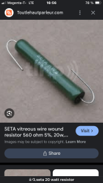
The wirewound 100k 1% 10W are about $8 each. Four needed for stereo, so $32 right there.
[Oops!] - I just checked the cupboards. I have 300k 2W metal film. I could parallel three of those to make 100k 6W. That should work .
No good?
The cost difference isn't much, though. These are $1.19 each, so $3.60 to make each 100k. Four needed for stereo, so $14.40 or so.
The wirewound 100k 1% 10W are about $8 each. Four needed for stereo, so $32 right there.
[Oops!] - I just checked the cupboards. I have 300k 2W metal film. I could parallel three of those to make 100k 6W. That should work .
Last edited:
- Home
- Amplifiers
- Tubes / Valves
- PP 6V6 amp from RCA RC-19 manual -- Thoughts?