I have no problem with an all in one design. I am merely admitting MY limitations in SMPS design.
My specks are 420Vdc @0.5A, -50Vdc @0.05A, 10V @9A. Switching at north of 50kHz. Some of those voltages need linear post filtering and that is included in my voltage list.
I am interested in the design process as much a the final outcome.
BTW, Cat was a reference to caterpillar, my cats always took more interest in laying on my books than reading them.
Cat was a reference to my Cat, called Cade, but sometimes I type stuff when Cade is not on the keyboard and notice later on that something subliminal might have happened. It was not intentional.
As I mentioned previously I caught what will be a minimum load problem. In respect of transformer design sometimes the headline criteria might get thrown in the bin, whilst taking care of those, due to other considerations.
In this case it is the transformer magnetising inductance. It has to get charged and discharged but as things are there is no path back. As such its energy still has to go somewhere and you end up with a minimum load.
https://www.tdk-electronics.tdk.com/inf/80/db/fer/etd_39_20_13.pdf
https://www.tdk-electronics.tdk.com/inf/80/db/fer/etd_44_22_15.pdf
etc.
Lmag will be the number of turns squared times the quoted material ungapped Al value. Something like 50 turns on an ETD39 gives you 20W. The same on an ETD44 gives you 6W. That's estimated from the spice model.
Without looking harder at the moment that will still be within a 200W and likely greater overall maximum power.
Another one that crops up is flux imbalance in the main transformer. Although it is current fed the flux is still subject to walking...
flux walking at DuckDuckGo
It's a bit late here but basically we add current sense resistors to each leg of the bridge and, not implemented, generate O/N with another PWM loop to keep things balanced. I'll update later.
New specification noted.
...
Attachments
Last edited:
Late for you, early for me. It is 6:13 AM, time for bed. I will study your links when I get up. My brain still works on NYC time.
Well I guess I could be more enthusiastic. I did actually build a mains to B+ SMPS and it worked...sort of-but not really. Id like to commit to the powersupply fully but it would have to wait at least a month before I can just throw away everything (school and sideways work (yes I called that sideways on purpose))
I totally agree upon doing the LTSpice simulatio before building the real deal. Unfortunately I have no idea how LTSpice works at all.
Above all my biggest limitation was the switching transformer. So far I couldnt find even some completely basic information about building one myself in home enviroment. And also my IC choice was pretty -lets be hones- not ideal.
So many things have gone wrong in my powersupplies I actually built quite a few before getting to a usefull one but all of them incorporated the GA3459 transformer actually not intended to fixed frequency operation and definitely not intended for the purpose I was using it.
In the begining I was playing arround completely discrete so I had a controller made of MCP602 that did all the PWM stuff and error ampliffication and then I had a feedback line coming out of it. Then I had a separate board with the transformer and fet. Kind of let me modify things real fast on the go and later I switched to a TL494 design which is horribly noisy but regulates the voltage incredibly well. Lacks ground isolation so if I connect a PC to it it bursts into a mess because I am too powering it with a ATX powersupply.
I agree on the subject of buying a powersupply that steps mains down to anywhere between 12-36V and then I would build a power supply that would convert that low voltage back again to HV. Yes I have the same feelings about this as you do- not really practicall with three power supplies anymore is it. Ever since I began on this I wanted to compactify and minimalise component count. Having one board would be much more efficient than a big fat hunka iron or three separate boxes to deal with.
I havent been able to progress on my work for 6 months now. And I just kindof got used to the horrible noise the power supply induces into my amplifier..after all on the levels I am listening it its not really all that noticeable and then the song ends and I get cry at the horrible noise. Id like to take this power supply to a whole diifferent level but my limitations are basically the anchor on my leg.
Also would it be possible to talk trough a different platform? Just so we have a more speedy way of communication
BTW in tubes if its a AB amplifier you can get away with 5V ripple. Trough the output stage nothing shows up really. And its not necessary to use very high frequencies aswell. After all a simple toroid core inductor LC filter (With a ceramic cap) would be perfectly ideal. Thats what I used in my first design which was quite but kept eating fets for breakfast. Remember filtering higher frequencies is easier. So ideally use switching frequencies above 25kHz. I found a bigger problem and that is to somehow prevent the transformer to make noise phisically. But that was more of a circuit problem on my side than anything really..
Well I guess I could be more enthusiastic. I did actually build a mains to B+ SMPS and it worked...sort of-but not really. Id like to commit to the powersupply fully but it would have to wait at least a month before I can just throw away everything (school and sideways work (yes I called that sideways on purpose))
Positive waves!
Not a T34 Tank Reference...
Just in case there is no fully commit. You have school stuff and more importantly Bees to take care of. It's not sideways stuff that you throw away. Let's be slow.Kelly: Nobody's asking you to be a hero. Oddball: No? Then YOU sit up in that turret baby. Kelly: No, because you're gonna be up there, baby, and I'll be right outside showing you which way to go. Oddball: Yeah? Kelly: Yeah. Oddball: Crazy… I mean like, so many positive waves… maybe we can't lose, you're on!
Last edited:
Bess are seasonal then I get a month break 🙂 . And then agriculture comes back up 😀 .
Ill be sure to dedicate my 3AM PC session to this subject. Still wondering about a faster way to communicate. I do have Facebook, Discord, Skype..
Ill be sure to dedicate my 3AM PC session to this subject. Still wondering about a faster way to communicate. I do have Facebook, Discord, Skype..
Hi,
LinearTechnology describes a couple of lownoise HV-supplies in AN118 "High Voltage, Low Noise, DC/DC Converters". Probabely not powerful enough, but maybe a basis to work with.
Linear also offers the LT3751, a quite flexible capacitor charger chip that can work as lownoise regulator also. We (company) use it in a automotive pulse tester to charge up to 20.000µF up to 300V within a few seconds. Looks quite promising to me as a dc-dc converter basis for line-level to power tube amp supplies.
jauu
Calvin
Thanks. That one crops up quite a lot but as you suggest they are low power. I believe Cat has already looked at something like the LT3751 using a stock transformer but ran into a few problems. We are going to be going kind of discrete in the initial stages but there may be a standard IC that will do some of the heavy lifting.
Well, I'm back. I have Facebook and Skype. No Discus. I've gone over some of the previous post. When I mentioned using a commercial line to LV, that was to take care of soft start, PFC, CE/UL concerns etc. But on the other end, one switcher can do all the other output voltages in one unit. From what I know(very little) an SG3525A would be useful. I like the fact it has a shutdown pin. I need that.
50kHz+ makes the transformer smaller, I think, and makes it easier to filter the output as well as it will push inband IM further away and lower in amplitude. Their may be other factors that make for a better choice,TBD.
As to PS ripple in an AB stage, I am not sure about it being immune. I do know it shows up in the IM sidebands as spikes at +- line freq. I just don't know how much is from the driver vs. output.
During startup, the min. load is the current heating the filaments, then the idle current of the output tubes and drivers.
Next for me is read the PDF's and watch this YouTube professor teach me about Magnetics.
OK. Let's say we have a team.
Morb: Manager.
Cat: Design Engineer.
Tubes: Customer.
As the Manager I get to ask stupid questions, make impossible demands and generally ensure that things will not work.
As the Design Engineer Cat gets dumped on and will have a miserable life.
As the Customer Tubes is always right but will end up being asked for a load of concessions and get a late delivered product that looks nothing like they thought they were getting.
There are no time scales. There is no pressure and, hopefully, no-one will get stressed out.
Cat has mentioned that they have not used Spice, LTSpice, before so let's start with that one.
LTspice | Design Center | Analog Devices
Download, install and run. Click on the Hammer. Click Drafting Options. Click Hot Keys. Your mind might work differently to mine but I change Rotate to Space and Mirror to X. You may/will have to change one of the others to avoid a conflict. Once done OK and OK to get back.
Click on the Play button top left for a new schematic. LTspice saves its schematics with a .asc extension. It also defaults to its install directory as the save location when first run. You don't want that so File|Save As then create your own spice work directory and navigate to it. Change the name from Draft1.asc to the usual meaningful thing and save. It will now default to saving in that directory unless you change things.
It should kind of make sense given you know electronics. The toolbar has buttons starting to the right of the print icon to draw a wire, place ground, place net, place resistor, place capacitor, place inductor, place capacitor and place component.
Place component brings up the bag of tricks. Top level are the grunt bits. Left of the pane are sublevels such as opamps where the complex fruity things live. The Top Directory will show as a path ending in /sym but if you click on the down arrow it will let you change it to your working directory.
On occasion you will have to download and use third party models or create symbols for them. It's kind of useful to place those in your working directory so you can access things easily from the component button.
I'm OCD, try to be tidy. Have a play.
As mentioned LTSpice saves things as .asc files. By the magic of the forum we get to go Advanced when we post messages and that gives you access to a Manage Attachments Button. It gives a list of what it will allow and the first one is asc.
As I suggest have a play with the software first. Then...
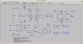
The proposed convertor is what is known in the trade as a Current Fed Bridge. They come in two flavours, Buck and Boost. This one is a Boost. The Boost Convertor is widely used for Power Factor Correction and the basic circuit is derived from the non-isolated version. That's what this model represents.
I know you, Cat, already know things but easy steps. I'll add some design words later.
...
Morb: Manager.
Cat: Design Engineer.
Tubes: Customer.
As the Manager I get to ask stupid questions, make impossible demands and generally ensure that things will not work.
As the Design Engineer Cat gets dumped on and will have a miserable life.
As the Customer Tubes is always right but will end up being asked for a load of concessions and get a late delivered product that looks nothing like they thought they were getting.
There are no time scales. There is no pressure and, hopefully, no-one will get stressed out.
Cat has mentioned that they have not used Spice, LTSpice, before so let's start with that one.
LTspice | Design Center | Analog Devices
Download, install and run. Click on the Hammer. Click Drafting Options. Click Hot Keys. Your mind might work differently to mine but I change Rotate to Space and Mirror to X. You may/will have to change one of the others to avoid a conflict. Once done OK and OK to get back.
Click on the Play button top left for a new schematic. LTspice saves its schematics with a .asc extension. It also defaults to its install directory as the save location when first run. You don't want that so File|Save As then create your own spice work directory and navigate to it. Change the name from Draft1.asc to the usual meaningful thing and save. It will now default to saving in that directory unless you change things.
It should kind of make sense given you know electronics. The toolbar has buttons starting to the right of the print icon to draw a wire, place ground, place net, place resistor, place capacitor, place inductor, place capacitor and place component.
Place component brings up the bag of tricks. Top level are the grunt bits. Left of the pane are sublevels such as opamps where the complex fruity things live. The Top Directory will show as a path ending in /sym but if you click on the down arrow it will let you change it to your working directory.
On occasion you will have to download and use third party models or create symbols for them. It's kind of useful to place those in your working directory so you can access things easily from the component button.
I'm OCD, try to be tidy. Have a play.
As mentioned LTSpice saves things as .asc files. By the magic of the forum we get to go Advanced when we post messages and that gives you access to a Manage Attachments Button. It gives a list of what it will allow and the first one is asc.
As I suggest have a play with the software first. Then...
The proposed convertor is what is known in the trade as a Current Fed Bridge. They come in two flavours, Buck and Boost. This one is a Boost. The Boost Convertor is widely used for Power Factor Correction and the basic circuit is derived from the non-isolated version. That's what this model represents.
I know you, Cat, already know things but easy steps. I'll add some design words later.
...
Attachments
Last edited:
Well, I'm back. I have Facebook and Skype. No Discus.
Good Morning, I suppose Evening, Tubes.
In terms of switching frequencies I'm looking at 100KHz for the Boost and 50KHz for the bridge. It may end up being slightly lower. 50KHz is the transformer frequency which translates to 100KHz at the output.
As I've hinted to begin with there is nothing solid about what IC as such to use. Cat has mentioned they have played and are happy with discrete implementations. Call it concept for the moment and we can try looking for application specific stuff later.
It's kind of what I am comfortable with. There are times when the application specific stuff does not fit your actual application and life becomes a pain as you try to bend it.
In terms of communications I'd like to keep it to the posts in the forum. Again, to me, there is no rush and no need to constantly be yammering at each other. Anything for a quiet life.
5V 12V 15V 18V 24V 36V 48V 60V Transformer 48W 60W 100W 120W 150W 180W 200W 300W 360W 400W 480W 500W 600W Switching Power Supply|Switching Power Supply| - AliExpress
I propose this as a CE certified starting point. Then the user can use there own LV supply, and it is 110/220 compliant. The question then becomes what voltage. I think 12 or 24V is a good point.
I propose this as a CE certified starting point. Then the user can use there own LV supply, and it is 110/220 compliant. The question then becomes what voltage. I think 12 or 24V is a good point.
Incoming boring words. Now we start to find out how bad my design decisions have been. In some respects this might seem trivial but...
The previous circuit shows a non-isolated boost convertor. We want to calculate the operating duty cycle. During switch, S1, on time Lboost is set through VIN. During switch off time Lboost is reset through (VOUT - VIN). In a PFC circuit inductor current will transition from discontinuous to continuous operation but we assume continuous operation.
The change in inductor current, dIL, is the voltage applied across it multiplied by the time it is applied divided by the inductance.
dIL = VL.T/L
dILset = VIN.TON/L
dILrset = (VOUT - VIN).TOFF/L
Steady state the average inductor current remains the same.
dILset = dILreset
VIN.TON/L = (VOUT - VIN).TOFF/L
The L's disappear.
VIN.TON = (VOUT - VIN).TOFF
Call TON the operating duty cycle D then TOFF becomes (1 - D). It normalises things to 1 second.
VIN.D = (VOUT - VIN).(1 - D)
VIN.D = VOUT - VOUT.D - VIN + VIN.D
VIN.D + VOUT.D - VIN.D = VOUT - VIN
VOUT.D = VOUT - VIN
D = (VOUT - VIN)/VOUT
The same sort of simple algebra applies to other square wave convertors. Consider the setting and resetting voltages and times, normalise and solve.
In the circuit I have assumed that all of the power ends up in the 420V output. That's another common thing to do. Make the assumption and tidy up later.
Tubes wants,
420V @ 0.5A = 210W
-50V @ 0.05A = 2.5W
10V @ 9A = 90W
Tubes is the customer so is right but... what's the 10V @ 9A for? I kind of guess heaters but showing my ignorance they are 6.3V/12.6V. Feel free not to tell.
Anyway that's more or less 300W. Now let's hurt ourselves and say the overall efficiency of the supply is going to be 80% but hope to do better. That makes the design power 360W.
Tubes wants operation from 90V to 270V AC which is the standard type of stuff for 110VAC and 240VAC line voltages. In the circuit I have picked 240V as a DC VIN. With VOUT at 420V that gives us our operating duty cycle as 42.8%. If you right click on the voltage source labelled DRV you will see it is set to give a 100KHz signal, 10uS period, with a 4.286uS on time.
Now we need a value for our Boost inductor. Rule of thumb is you operate at 20%-40% ripple current and in this particular case err towards 40%. 360 watts from 240V is an average current of 1.5A so 40% ripple is 0.6A. Since we know TON, VIN and dIL we get to calculate the value of the inductor as being 1.7mH.
It's not hard and fast but rather a starting point. With VIN at 110V average current will be higher, have to account for that when considering saturation, and ripple will be lower. This sort of stuff is always subject to optimisation.
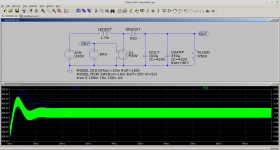
Looking back at the circuit. S1 and DBoost come with .MODEL statements. These are ideal components. CFILT has a value of 100u for no particular reason and, Spice does this thing where it shouts up unexpected results, I've added CDAMP with an ESR of 4R7, sort of SQRT(LBoost/CFilt). The circuit is open loop so there is an undamped resonance between LBOOST and CFILT. CDAMP should not be necessary in the end result.
If you right click on CDAMP you will see the setting for the ESR. The other setting for both capacitors is an Initial Condition, IC, that sets the start up voltage to 420V for both of them. You have to CTRL Right Click to see those. Right click on the x to set/clear whether they are displayed.
The IC statements go hand in hand with the .tran analysis statement which has uic, Use Initial Conditions, tagged onto it. Generally speaking with SMPS circuits you always set that otherwise it goes off and tries to find a DC operating point for an hour before losing the plot and giving up.
The previous circuit shows a non-isolated boost convertor. We want to calculate the operating duty cycle. During switch, S1, on time Lboost is set through VIN. During switch off time Lboost is reset through (VOUT - VIN). In a PFC circuit inductor current will transition from discontinuous to continuous operation but we assume continuous operation.
The change in inductor current, dIL, is the voltage applied across it multiplied by the time it is applied divided by the inductance.
dIL = VL.T/L
dILset = VIN.TON/L
dILrset = (VOUT - VIN).TOFF/L
Steady state the average inductor current remains the same.
dILset = dILreset
VIN.TON/L = (VOUT - VIN).TOFF/L
The L's disappear.
VIN.TON = (VOUT - VIN).TOFF
Call TON the operating duty cycle D then TOFF becomes (1 - D). It normalises things to 1 second.
VIN.D = (VOUT - VIN).(1 - D)
VIN.D = VOUT - VOUT.D - VIN + VIN.D
VIN.D + VOUT.D - VIN.D = VOUT - VIN
VOUT.D = VOUT - VIN
D = (VOUT - VIN)/VOUT
The same sort of simple algebra applies to other square wave convertors. Consider the setting and resetting voltages and times, normalise and solve.
In the circuit I have assumed that all of the power ends up in the 420V output. That's another common thing to do. Make the assumption and tidy up later.
Tubes wants,
420V @ 0.5A = 210W
-50V @ 0.05A = 2.5W
10V @ 9A = 90W
Tubes is the customer so is right but... what's the 10V @ 9A for? I kind of guess heaters but showing my ignorance they are 6.3V/12.6V. Feel free not to tell.
Anyway that's more or less 300W. Now let's hurt ourselves and say the overall efficiency of the supply is going to be 80% but hope to do better. That makes the design power 360W.
Tubes wants operation from 90V to 270V AC which is the standard type of stuff for 110VAC and 240VAC line voltages. In the circuit I have picked 240V as a DC VIN. With VOUT at 420V that gives us our operating duty cycle as 42.8%. If you right click on the voltage source labelled DRV you will see it is set to give a 100KHz signal, 10uS period, with a 4.286uS on time.
Now we need a value for our Boost inductor. Rule of thumb is you operate at 20%-40% ripple current and in this particular case err towards 40%. 360 watts from 240V is an average current of 1.5A so 40% ripple is 0.6A. Since we know TON, VIN and dIL we get to calculate the value of the inductor as being 1.7mH.
It's not hard and fast but rather a starting point. With VIN at 110V average current will be higher, have to account for that when considering saturation, and ripple will be lower. This sort of stuff is always subject to optimisation.
Looking back at the circuit. S1 and DBoost come with .MODEL statements. These are ideal components. CFILT has a value of 100u for no particular reason and, Spice does this thing where it shouts up unexpected results, I've added CDAMP with an ESR of 4R7, sort of SQRT(LBoost/CFilt). The circuit is open loop so there is an undamped resonance between LBOOST and CFILT. CDAMP should not be necessary in the end result.
If you right click on CDAMP you will see the setting for the ESR. The other setting for both capacitors is an Initial Condition, IC, that sets the start up voltage to 420V for both of them. You have to CTRL Right Click to see those. Right click on the x to set/clear whether they are displayed.
The IC statements go hand in hand with the .tran analysis statement which has uic, Use Initial Conditions, tagged onto it. Generally speaking with SMPS circuits you always set that otherwise it goes off and tries to find a DC operating point for an hour before losing the plot and giving up.
Without disrespect towards all contributors to this thread who may be more knowledgeable than me, I would like to add my post.
Cathode Ray Tubes used higher voltages compared to thermionic valves as used in residences. I remember a TV set with a high tension DC of 32,000V. These used a voltage multiplier and a high tension transformer and the circuits are available, well tested and well tried. I think, one can extract the EHT generating circuit from CRT TVs and modify it to produce the required voltage of 1000V.
Cathode Ray Tubes used higher voltages compared to thermionic valves as used in residences. I remember a TV set with a high tension DC of 32,000V. These used a voltage multiplier and a high tension transformer and the circuits are available, well tested and well tried. I think, one can extract the EHT generating circuit from CRT TVs and modify it to produce the required voltage of 1000V.
5V 12V 15V 18V 24V 36V 48V 60V Transformer 48W 60W 100W 120W 150W 180W 200W 300W 360W 400W 480W 500W 600W Switching Power Supply|Switching Power Supply| - AliExpress
I propose this as a CE certified starting point. Then the user can use there own LV supply, and it is 110/220 compliant. The question then becomes what voltage. I think 12 or 24V is a good point.
Sorry. Typing while you posted. More is better but in terms of regulations/standards you would still have to deal with the Low Voltage Directive for DC up to 75V and you still have the final 420V output. Whichever way you go if you are going to sell product commercially and honestly you will get hit. Consider it a bridge to be crossed.
The suggested topology should be able to operate or be designed to do so with a 24V input. The sums will be more or less the same. As with the off-line suggestion it's a bit you don't know until you look at it. The problem is that the project bifurcates and Cat gets dumped on.
Blub. Conflict already.
End of day it kind of depends on what Cat is happy with. Sorry, with management hat on the engineer is key.
Last edited:
Pops out for a smoke. Cat has already been through this sort of design cycle, pain, and got caught out by having to boost low voltages to high ones. It does not really scale the right way because you are dealing with high boost ratios. I'll have a look but in part that's my limitation. Otherwise it's falling down into the recreate the e-bay stuff to end up with a result that will be like the e-bay stuff so why not just buy the e-bay staff? To me that's not part of Cat's ethos.
- Home
- Amplifiers
- Power Supplies
- Powerful SMPS for tube ampifier