Never can have enough donuts!
The mailman already thinks I am crazy anyway.
I have been aware of Ms. Parker's work for almost twenty years. Would love to hear one of those amplifiers.

Are you aiming at 60V regulated output? In that case, omit RF filter. Murata does specify it would withstand 120V for a short time, but does not give any expected lifetime at more than 50V. At 0.2 – 0.5A loads, C2 at 4700 uF with 80 – 100V rating would be fine.I should probably bite the bullet and order a transformer with a 50V secondary.
Are you aiming at 60V regulated output? In that case, omit RF filter. Murata does specify it would withstand 120V for a short time, but does not give any expected lifetime at more than 50V. At 0.2 – 0.5A loads, C2 at 4700 uF with 80 – 100V rating would be fine.
I will take anything between 55 and 60V. I am trying to identify a good transformer for that target. The above I posted is completely ridiculous for that current draw.
I agree in more than one way. It is the traditional 'donut time of the year' in Croatia. With carnival approaching, donuts are the mandatory treat. This weekend I enjoyed over 20 home made donuts, right from the pan. Beer was there only to help with donuts. 🙂Never can have enough donuts!
How about this Triad one:

Or this Antek one:

In series in both cases.
I tend to prefer Antek, but the Triad one looks more appropriate.
Or this Antek one:
In series in both cases.
I tend to prefer Antek, but the Triad one looks more appropriate.
OK, as an orientation point, transformer loaded at 1/3 of declared VA, will provide some 1.27 x AC at the first reservoir capacitor. 50V secondary, under that conditions would provide some 63-64 V at the regulator input. To account for mains voltage variation, probably 3-5V over regulator would be required. Even with zero load, at C2 voltage would nor go over 70V and output target can be 58 - 60V. If your mains deviates a lot from nominal (solar power plant near) that should be taken into the account. With less load, more voltage at C2 as well (not a problem for the regulator part).I will take anything between 55 and 60V. I am trying to identify a good transformer for that target. The above I posted is completely ridiculous for that current draw.
Seems fine if it is 2 X 25V. What is typical mains voltage in your area. 25V output is specified for 120V input.How about this Triad one:
Seems fine if it is 2 X 25V. What is typical mains voltage in your area. 25V output is specified for 120V input.
It varies by season. Tends to be 115V in the Summer and 120V in the Winter.
You are right, the Antek is tested at 120V, but is in fact 2 X 24V.
I also found this one:
https://www.antekinc.com/content/AS-1224.pdf
Which I like even better because of the shield between primaries and secondaries. It is also 2 X 24V.
Then, it is safe to use 50V (2x25 at no load) as input voltage at C2 and LT4320 will not surpass 70V under any conditions, worst case being during winter and no load at the supply output.It varies by season. Tends to be 115V in the Summer and 120V in the Winter.
Then, it is safe to use 50V (2x25 at no load) as input voltage at C2 and LT4320 will not surpass 70V under any conditions, worst case being during winter and no load at the supply output.
It will never be at no load in practice, so even though that 2X24V Antek gives 25V at no load, my guess is it'll give between 24.5 and 25V at something like 0.25 A. In other words, it should be fine.
I think I am settling on:
https://www.antekinc.com/content/AS-1224.pdf
@Vunce Do you concur? (movie reference; 10 points to anyone who guesses)
EDIT: I sent an email to Antek to have them confirm what kind of Load Test characteristics I can count on if I wire the secondaries in series.
Last edited:
BTW, @tombo56, thank you so much for all your help and support in this thread! You are doing a great service to the community as solutions of this quality at that voltage output are few and far in between!
Last edited:
Thank you for the kind words but, as said before, I’m only returning the favor to this community.

Another board assembled. Finished this one yesterday. Got frustrated messing with the heatsink clip and just drilled and tapped a hole to screw-mount the MOSFET.
Power transformer is in the mail; haven't actually tested it yet. Was fun to do some SMD soldering by hand; only had to fix one little solder bridge on the tiny op-amp. Glad @tombo56 advised soldering that part last; absolutely the right advice.
Thanks for the hard work on this design, looking forward to trying it out.
Attachments
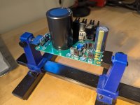
Additional work, but definitely better thermal transfer for the MOSFET.Got frustrated messing with the heatsink clip and just drilled and tapped a hole to screw-mount the MOSFET.
Definitely worth it. I spent more time messing with the clip than I did drilling and tapping one measly little hole, for which I didn't even bother with the drill press. Highly recommend this approach for others building the board, provided you have a suitably sized drill bit and tap available.Additional work, but definitely better thermal transfer for the MOSFET.
- Home
- Amplifiers
- Power Supplies
- Power Supply with Active Rectifier, RF Filter and Super-Regulator