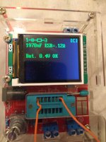
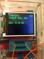
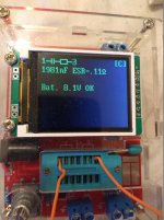
lol what does that mean?
Replace it?
If so can I just put a cap across it? Not even sure I have something like that
Replace it?
If so can I just put a cap across it? Not even sure I have something like that
Not paralleled, that wouldn't prove anything. Remove the old one, install a new one.
Anything rated at 250V or more, and from 0.5uF to 5uF. You gotta have something.
Anything rated at 250V or more, and from 0.5uF to 5uF. You gotta have something.
Last edited:
Remove the valve(s), remove one end of both 2.2u capacitors and measure the output voltage. The 1M5 resistor and the capacitors perform a slow start function which brings up the HT slowly allowing the cathodes time to heat up before applying the full HT. If either of the caps is leaky then the 1M5 resistor and the leakage resistance will form a voltage divider. O0ps, just seen that Goat Guy has explained this function.
Last edited:
Hi,
Should I remove the ground side or the other?
I will try and measure the capacitor out of circuit
Should I remove the ground side or the other?
I will try and measure the capacitor out of circuit
So…
After looking carefully at the diagram in the first post, I am revising my assemssment of the Q200 complex of diodes and so on.
The diode is not the 1N4748 (which would be a 22 volt zener), but the 1N4148 (common ordinary diode), which at a few milliamps will have a VFORWARD of about 0.7 V per diode. And they are forward biased. Ultimately they're acting as a relatively stable 1.4 V source. In conjunction with the R204 emitter-self-bias resistor of 120 Ω, and the normal VEBO forward voltage drop of the bipolar transistor, this leaves 0.7 V for the 121 Ω resistor to make up.
The 0.00579 amps flows into the Zener stack at the bottom of the diagram, which as said before is
So… constant current, Zener stack, becomes a voltage reference of surprisingly low impedance. The 100 Ω resistor connected in series is of nearly no importance. Cool!
________________________________________
IF any of the C202, C203 or LC203 capacitors has 'gone', then their reduced impedance would very likely result in the 16 V (or lower…) that you observe with your meter.
________________________________________
WAIT… I just had an ah-hah! thought.
See those Zener gate-protection diodes, for the MOSFETs? The VZENER working voltage for the 1N4744 is only 15 volts. Hey… 15 is close to 16! Ah… and now it becomes abundantly clear.
Either C203 or LC203 has shorted out. OR the load on that channel is presesnting a short. In any case, the 15 volt gate-proection Zener is firing, and raising the ground-potential (of a short) to +15 to +16 volts.
This in turn, being quite low impedance presents at the pin you've been measuring as 16 V.
________________________________________
This has to be it, I think. Sure, a MOSFET could be damaged, or something. But ultimately the coincidence of the VZ Zener protection diodes and the measured value, indicates a short.
Anyway, probably what someone else said, earily.
If so, I apologize.
⋅-⋅-⋅ Just saying, ⋅-⋅-⋅
⋅-=≡ GoatGuy ✓ ≡=-⋅
After looking carefully at the diagram in the first post, I am revising my assemssment of the Q200 complex of diodes and so on.
The diode is not the 1N4748 (which would be a 22 volt zener), but the 1N4148 (common ordinary diode), which at a few milliamps will have a VFORWARD of about 0.7 V per diode. And they are forward biased. Ultimately they're acting as a relatively stable 1.4 V source. In conjunction with the R204 emitter-self-bias resistor of 120 Ω, and the normal VEBO forward voltage drop of the bipolar transistor, this leaves 0.7 V for the 121 Ω resistor to make up.
E = IR
0.7 = I × 121
I = 0.00579 amp
Good. This is a near-constant-current source, as well. Nice. 0.7 = I × 121
I = 0.00579 amp
The 0.00579 amps flows into the Zener stack at the bottom of the diagram, which as said before is
VTOT = 39 + 62 + 62 + 62
VTOT = 225 V
And it is properly biased at about 5 mA, or about 300 mW per 62 V Zener. Not too much. The Zeners are rated (insofar as Mouser is concerned) at 1300 mW apiece.VTOT = 225 V
So… constant current, Zener stack, becomes a voltage reference of surprisingly low impedance. The 100 Ω resistor connected in series is of nearly no importance. Cool!
________________________________________
IF any of the C202, C203 or LC203 capacitors has 'gone', then their reduced impedance would very likely result in the 16 V (or lower…) that you observe with your meter.
________________________________________
WAIT… I just had an ah-hah! thought.
See those Zener gate-protection diodes, for the MOSFETs? The VZENER working voltage for the 1N4744 is only 15 volts. Hey… 15 is close to 16! Ah… and now it becomes abundantly clear.
Either C203 or LC203 has shorted out. OR the load on that channel is presesnting a short. In any case, the 15 volt gate-proection Zener is firing, and raising the ground-potential (of a short) to +15 to +16 volts.
This in turn, being quite low impedance presents at the pin you've been measuring as 16 V.
________________________________________
This has to be it, I think. Sure, a MOSFET could be damaged, or something. But ultimately the coincidence of the VZ Zener protection diodes and the measured value, indicates a short.
Anyway, probably what someone else said, earily.
If so, I apologize.
⋅-⋅-⋅ Just saying, ⋅-⋅-⋅
⋅-=≡ GoatGuy ✓ ≡=-⋅
He said he checked all the Zeners, so odds are it's a short circuit load, like a capacitor
or other circuit element, or a pcb fault. You'd think the related fet would fail or be hot, though.
or other circuit element, or a pcb fault. You'd think the related fet would fail or be hot, though.
- Home
- Amplifiers
- Tubes / Valves
- Power supply fault in preamp


