Gonna have to disconnect the audio circuit and use resistor loads, maybe 47k 2W on each output.
See if it is still 15VDC with only the load resistors.
See if it is still 15VDC with only the load resistors.
Last edited:
yes, the zener string voltage looking at the gates of the mosfets minus about 4 volts is the source voltage.....this is the design, and changes in line voltage will keep the output voltage constant with load...
your load being a class A, will never vary, so i wonder, a crcrc filter would have been better,
thus far i have resisted the urge to use voltage regulators in my tube amps...
but this one being a mosfet source follower can be an exception, having no voltage gains by itself and all.....carry on....
your load being a class A, will never vary, so i wonder, a crcrc filter would have been better,
thus far i have resisted the urge to use voltage regulators in my tube amps...
but this one being a mosfet source follower can be an exception, having no voltage gains by itself and all.....carry on....
Gonna have to disconnect the audio circuit and use resistor loads, maybe 47k 2W on each output.
See if it is still 15VDC with only the load resistors.
or a 100k resistor...a temporary load...
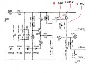
Can you please explain what is going on with the MOSFET?
The Gate is suppose to open and let power through but I can't understand it to save my life!
On message #34 I drew the G D S on the MOSFET and the voltages. Is the Gate open? Is it letting the power through?
The Gate is suppose to open and let power through but I can't understand it to save my life!
On message #34 I drew the G D S on the MOSFET and the voltages. Is the Gate open? Is it letting the power through?
The fet is voltage controlled (electric field), so no current or power goes through the gate. Like a tube.
https://www.ti.com/lit/an/snva008/s...20736&ref_url=https%3A%2F%2Fwww.google.com%2F
https://www.ti.com/lit/an/snva008/s...20736&ref_url=https%3A%2F%2Fwww.google.com%2F
Last edited:
Can you please explain what is going on with the MOSFET?
The Gate is suppose to open and let power through but I can't understand it to save my life!
On message #34 I drew the G D S on the MOSFET and the voltages. Is the Gate open? Is it letting the power through?
the drain source terminal is like a variable power resistor that changes its resistance in reaction to a voltage at its gate...
putting in a new or fresh mosfet is not entirely a bad idea...
without the mosfet in circuit, you can measure the voltage across the zener strings, that will be the voltage at the gate of the mosfet...
patience is a virtue here...
Thanks for all the input.....
I did watch a few videos on how MOSFETs work but my brain just can't work it out.
I have already taken a few measurements. Ok maybe I shouldn't try and understand it as its beyond me but I'm just trying to find out what is wrong with the voltages!
I did watch a few videos on how MOSFETs work but my brain just can't work it out.
I have already taken a few measurements. Ok maybe I shouldn't try and understand it as its beyond me but I'm just trying to find out what is wrong with the voltages!
Attachments
it is really up to you now, we have given you all you need to know...
Think you've caused some trauma.
just a tip, why not ask the manufacturer for help? they should be able to support their products in the first place...
do not allow the problem stump you, persevere....patience is key....
once you fix the problem, you can tell yourself, it was not so hard after all..
do not allow the problem stump you, persevere....patience is key....
once you fix the problem, you can tell yourself, it was not so hard after all..
It appears I am ungrateful for the advice..quite the opposite!
Going to fine comb it tomorrow. It may have been even answered already but I dont understand it!
The mission continues.......I will update progress
Going to fine comb it tomorrow. It may have been even answered already but I dont understand it!
The mission continues.......I will update progress
Going to fine comb it tomorrow. It may have been even answered already but I dont understand it!
It's after the 1.5M for sure, and is more likely to be a short than an open.
Last edited:
No broken tracks around the PSU area. Checked all connections. Not sure about shorts, I think if there was one there will be smoke but none so far!
Agreed. If something was shorted you'd know in a hurry.
Just checked all the resistors after the main power MOSFETs and they pretty much all check out except a few that I believe is measuring wrong as its in circuit. Both sides checked the same thus my conclusion.
I'm going to put the caps back in and have another look at the voltages
I'm going to put the caps back in and have another look at the voltages
Put the caps back. Measure a few components, nothing tested faulty in circuit.
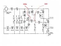
Power it back on and still 13-14 volts where is there is suppose to be 250v! 😕
Power it back on and still 13-14 volts where is there is suppose to be 250v! 😕
Progress!!............
ZD204 tested perfect in circuit but after replacing it the unit powered up!
Unfortunately it only lasted about 5 minutes before both the Zeners blew.
Both LZD204 and ZD204 made a loud snapping noise and now the meter on diode mode gives me reading in both direction where previously it didn't.
Any suggestions what would cause it to blow? I have made progress in at least getting it to work but now need advice on what what cause the Zener to blow like that.
As always any advice appreciated!
Attachments
- Home
- Amplifiers
- Tubes / Valves
- Power supply fault in preamp