Please help!
I have no experience with tubes and I'm stuck on a problem. I've had a preamp for a while by Assembelage L-1
There is no high voltage and I cant figure out what is going on. I have tested all resistors and caps and diodes. I bought a nice transistor tester from China that tell me my Mosfets are fine but it doesn't even get that far.
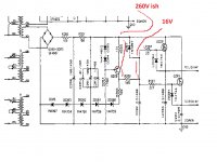
the problem is before the resistor marked 1M5 there is very high voltage but after is only 16v! Its not supposed to be that low. Please what is going on? I waited a week for the resistor only to find the same result!
Any help appreciated!
I have no experience with tubes and I'm stuck on a problem. I've had a preamp for a while by Assembelage L-1
There is no high voltage and I cant figure out what is going on. I have tested all resistors and caps and diodes. I bought a nice transistor tester from China that tell me my Mosfets are fine but it doesn't even get that far.
the problem is before the resistor marked 1M5 there is very high voltage but after is only 16v! Its not supposed to be that low. Please what is going on? I waited a week for the resistor only to find the same result!
Any help appreciated!
Attachments
Have you tried removing just one fet at a time? Sure about fet pinouts?
Sure the fets' Zeners are in the right way? Is this loaded or unloaded?
The circuit before the 1.5M seems to be operating ok.
It would appear that something after the 1.5M is the problem.
Are the fet heat sinks grounded? Is there measured high impedance
isolation from the fet sink to the drain?
Sure the fets' Zeners are in the right way? Is this loaded or unloaded?
The circuit before the 1.5M seems to be operating ok.
It would appear that something after the 1.5M is the problem.
Are the fet heat sinks grounded? Is there measured high impedance
isolation from the fet sink to the drain?
Last edited:
Tested voltages without Mosfets? Also check without the GS zenners, A digital multimeter will sag a bit the voltage because its internal impedance, but not so low as your readings, that 1.5M resistor is in the high side, a 100-200k would do in that spot, also the 2.2uF capacitors could be leaking. The 1.5M should cause the supply to make a HT delay ramp of almost 4 seconds to full zenner stack voltage supposing the other components are good.
Q200 is 2sa1142
According to the data sheet the collector to base voltage is -180 but it has 360 going
into the Base from D204. Is that normal?
Probably normal for the circuit, the rail is just 2 diode drops more positive than the base.
The collector is elevated in potential well above ground by the Zener string.
Label all the nodal DC voltages on the schematic, and it will be more clear to you.
Last edited:
...before the resistor marked 1M5 there is very high voltage but after is only 16v!...
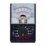
What kind of meter??
The 16V with the other values suggests 100k loading there. I have seen Electrician's Meters that low. There are also needle-meters at 2k/V, which on 50V scale would be 100k.
Meter type, brand, and model number.
Attachments
Last edited:
Thanks so much for the reply but its all too technical.
I have 2 days back replaced both the MOSFETS.
So hold on everything is fine before the 1M5? so why is there only 16v after and why is nothing smoking due to the super voltages?
Where is all that voltage going?
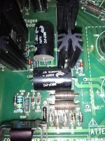
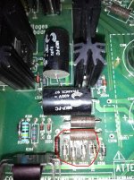
I'll upload a pic now
I have 2 days back replaced both the MOSFETS.
So hold on everything is fine before the 1M5? so why is there only 16v after and why is nothing smoking due to the super voltages?
Where is all that voltage going?
I'll upload a pic now
I'll assume your 260 V and 16 V measurements are relative to common (black, negative lead on multimeter).
!5 the bottom of R205 (or end of the Zener stack), you ought to have about (62 + 62 + 62 + 39 → 225) volts. If the point above R205 is 260 V, and if the value of R206 is 100 Ω, then the difference is ( 260 - 225 → 35) volts. 35 across a 100 Ω resistor is (E = IR … 35 = 100 I … I → 350 mA). That, boys'n'girls is HUGE.
Huge, for the sole purpose of setting up a reasonable mid-voltage 'standard' for the gates of the MOSFETs individually acting as series voltage regulators.
Can we confirm that R205 and R204 are 15 watt resistors? They would need to be. Again, to absolutely no useful purpose, except increasing the amount of ripple fed into LQ201 and Q201.
At any rate, if you are seeing 16 V at the right-side of R206 which is 1.5 MΩ, then by similar calculation, ΔE = IR … (260 - 16 → 244 Volts) = I × 1,500,000 … I = 244 ÷ 1.5×10⁶ … I → 0.163 mA
Well, there you are. As RayMa alludes to, something on the right side, the LQ and Q MOSFETs, is sucking up 0.16 mA across that 1.5 MΩ resistor. Hard to say what it is, until you remove one of them.
Personally, I would have thought R204, 205 would be more like 10 to 12 kΩ each, and moreover, the whole wasteful voltage-setpoint configuration would just be the pair of 1N4748 Zeners in series with the pair of 10 kΩ resistors, forming a combination of Zener load, and high voltage divider.
DO NOTE that the point of the 1.5 MΩ resistor is to form a slow-turn-on charge function to the C202 2.2 µF ÷ 400 V capacitor. Indeed, at turn-on the charge current will be around 0.17 mA. RC = 1.5×10⁶ × 2.2×10⁻⁶ → 3.3 seconds. This means every 3.3 seconds, the charge-voltage on C202 is (1 - 1/e) or 63% closer to the (300+ - 225 → 75 ÷ 2 ) + 225 ⇒ 260 volts of the midpoint between the two zener chains. VERY slow turn-on.
Anyway, there are far smarter people lurking here, that'll check this hypothesis.
⋅-⋅-⋅ Just saying, ⋅-⋅-⋅
⋅-=≡ GoatGuy ✓ ≡=-⋅
I'll assume your 260 V and 16 V measurements are relative to common (black, negative lead on multimeter).
!5 the bottom of R205 (or end of the Zener stack), you ought to have about (62 + 62 + 62 + 39 → 225) volts. If the point above R205 is 260 V, and if the value of R206 is 100 Ω, then the difference is ( 260 - 225 → 35) volts. 35 across a 100 Ω resistor is (E = IR … 35 = 100 I … I → 350 mA). That, boys'n'girls is HUGE.
Huge, for the sole purpose of setting up a reasonable mid-voltage 'standard' for the gates of the MOSFETs individually acting as series voltage regulators.
Can we confirm that R205 and R204 are 15 watt resistors? They would need to be. Again, to absolutely no useful purpose, except increasing the amount of ripple fed into LQ201 and Q201.
At any rate, if you are seeing 16 V at the right-side of R206 which is 1.5 MΩ, then by similar calculation, ΔE = IR … (260 - 16 → 244 Volts) = I × 1,500,000 … I = 244 ÷ 1.5×10⁶ … I → 0.163 mA
Well, there you are. As RayMa alludes to, something on the right side, the LQ and Q MOSFETs, is sucking up 0.16 mA across that 1.5 MΩ resistor. Hard to say what it is, until you remove one of them.
Personally, I would have thought R204, 205 would be more like 10 to 12 kΩ each, and moreover, the whole wasteful voltage-setpoint configuration would just be the pair of 1N4748 Zeners in series with the pair of 10 kΩ resistors, forming a combination of Zener load, and high voltage divider.
DO NOTE that the point of the 1.5 MΩ resistor is to form a slow-turn-on charge function to the C202 2.2 µF ÷ 400 V capacitor. Indeed, at turn-on the charge current will be around 0.17 mA. RC = 1.5×10⁶ × 2.2×10⁻⁶ → 3.3 seconds. This means every 3.3 seconds, the charge-voltage on C202 is (1 - 1/e) or 63% closer to the (300+ - 225 → 75 ÷ 2 ) + 225 ⇒ 260 volts of the midpoint between the two zener chains. VERY slow turn-on.
Anyway, there are far smarter people lurking here, that'll check this hypothesis.
⋅-⋅-⋅ Just saying, ⋅-⋅-⋅
⋅-=≡ GoatGuy ✓ ≡=-⋅
Those resistors are not 15 watts more like 1 or 2.
I measured either side of R205 with ground and its 250V on either side
My meter is Chinese but didnt flag up any faulty diodes in circuit
PRR's question was about the voltmeter you are using, not the transistor tester. If it is a mechanical analogue meter it might have a low impedance, like 100 KOhm on the scale you are using, and that could explain your 16V reading on the right-hand side of the 1.5 MOhm resistor.
No its digital and I regret buying it!
UNI-T UT61
OK, it looks like it's about 10 Mohm input impedance, so that doesn't seem to be the problem with the 16V measurement you are getting.
Load one of the outputs with a 100k resistor that is in series with a 10k resistor going to ground.
Use your meter to measure the voltage across the 10k resistor.
Is the voltage now roughly 10% of the right output voltage?
If so, it's your meter that is the problem, not the circuit.
As said, it is excessively loading the node after the 1.5M when measuring the voltage there.
For tube circuits you will need a high impedance meter.
This sound like I can very easily electrocute myself 😱
Can I just measure some more stuff in circuit?
I appreciate all help as the initial problem is I'm not getting any sound and the reason for that is the missing high voltage!
Never hook up to your system a circuit under development until it is very well tested first.
Don't just try it, to see if it works. Most of the time it won't, and it could take out other
equipment in the system, sometimes in a spectacular fashion. Get some basic test equipment,
even if it has to be used/cheap.
Don't just try it, to see if it works. Most of the time it won't, and it could take out other
equipment in the system, sometimes in a spectacular fashion. Get some basic test equipment,
even if it has to be used/cheap.
Last edited:
- Home
- Amplifiers
- Tubes / Valves
- Power supply fault in preamp