You may find this interesting 🙁
"AFAIK the UJN parts are reliable, but the linear performance of the ones
I tested was not particularly good."
Interfet "Japanese Equivalent JFET Types"
"AFAIK the UJN parts are reliable, but the linear performance of the ones
I tested was not particularly good."
Interfet "Japanese Equivalent JFET Types"
Both SJDP120R085 and UJ3N06580 are regular SIC JFETs characterized by high output impedance while SITs have low output impedance on common source. Each needs a distinctly different optimization strategy to work its best. NP shows preference of using SITs without loop feedback. 🙂... Plus the Semisouth SJDP120R085, widely regarded as a SIT in this forum, is termed "Trench Silicon Carbide Power JFET" in the datasheet, ...
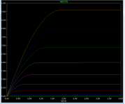
Curve traces for uj3n65080 from manufacturer's spice model. Vg is stepped from -10V to -8.4V in 200mV increments.
It doesn't look all that triode-like to me 🙁
It doesn't look all that triode-like to me 🙁
Attachments
Last edited:
Member
Joined 2009
Paid Member
JFET is like a Pentode, the 'plate curves' are convex and show typical transistor like behaviour, whereas the SIT is like a triode, the 'plate curves' are concave. The JFET has v. high input impedance but many SITs have gate leakage and they are hard to make - sensitive to manufacturing process variations just like high gm triodes.
You can 'triode wire' the JFETs to reduce output impedance (drain to gate feedback).
You can 'triode wire' the JFETs to reduce output impedance (drain to gate feedback).
Last edited:
Member
Joined 2009
Paid Member
The SJDP120R085 part looks nice but the capacitance is too high for what I'd like to use it for.
It doesn't look all that triode-like to me 🙁
Also not very physically real, looks like level 1 model with no Vds modulation of drain current at all. Doesn't even remotely match the DS which shows almost pure triode behavior below 5V Vds.
Last edited:
Also not very physically real, looks like level 1 model with no Vds modulation of drain current at all. Doesn't even remotely match the DS which shows almost pure triode behavior below 5V Vds.
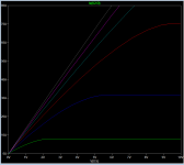
Indeed, replicating the datasheet Fig. 2 conditions, with Vgs stepped from 2V to -8V yields dissimilar curves. Maybe I am doing something wrong as the manufacturer's spice model seems quite detailed.
At least, for once reality seems better than simulation 😱, and this raises my hopes again!
Attachments
Last edited:
At least, for once reality seems better than simulation 😱, and this raises my hopes again!
Another problem with the DS is that it shows curves going to 40A and 10V = 400W like it was no problem.
Another problem with the DS is that it shows curves going to 40A and 10V = 400W like it was no problem.
I don't think this a problem as the datasheet does not claim that this is continuously dissipated power. I would think that 40A and higher are within the pulsed capabilities of the device. SOA is also stated.
I see nothing wrong with the datasheet.
Normally on ?
Too risky !
How right you were Nigel! Now try imagining this in a circlotron topology and there you have it: hell on earth! The dodgy temp coefficient seems like child's play in comparison.
Attachments
We work with a friend. Just started.
We continue to develop an early topic:
JFET-only Headphone Amp "Circlotron КП903B".
We continue to develop an early topic:
JFET-only Headphone Amp "Circlotron КП903B".
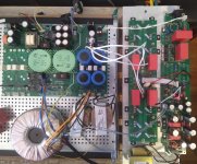
Trial version of amplifier with SI-C JFET.
The whole previous part is also on JFET.
https://www.diyaudio.com/forums/sol...clotrons-negative-feedback-3.html#post6134674
Thanks.
The whole previous part is also on JFET.
https://www.diyaudio.com/forums/sol...clotrons-negative-feedback-3.html#post6134674
Thanks.
Trial version of amplifier with SI-C JFET.
On MOSFET, the circuit works perfectly, it remains only to buy JFET UJ3N065080K3S. Very interesting how they sound.🙂

 Congratulations and thanks for the video
I just found this thread. I'm also very impressed by the sound of this amp. Well done! Any updates or luck acquiring and testing the UJ3N065080K3S?
Just come across this thread. I seem to remember some earlier smaller power jfets being tried by NP and others. I think the number was LU1040D or something like that. The main idea was to run them in the resistive region where they were very linear.
Scott.s earlier comment could mean that these new ones could be run in a similar way ie low Vds ?. As with the earlier devices that would mean cascode operation.
Is this feasible ?
Scott.s earlier comment could mean that these new ones could be run in a similar way ie low Vds ?. As with the earlier devices that would mean cascode operation.
Is this feasible ?
Last edited:
- Home
- Design & Build
- Parts
- Power JFETs in production