I will not sell anything, I will order some pcb and built the amp. You can get the gerber files in a zip file. But no guarantee for working. Its your own risk.
If you send me a PM, i send you the zip file. I do not want to share the zip file public. I will give you a notice.
Perhaps Hennady can have a last look ?
The kits i have ordered to make measurements of some holes. I have built the original LJM L20SE and want to use the holes in the heatsinks, no new drilling. The kits are cheaper as buying the parts in different shops. One shop will not be enough, so my experience. Some parts i have still at home.
I made it just for fun. I am a pensioner since a few years and i have something to do with my brain...not really knowing much in electronic, i am learning every day. All i know i have i learned by myself. Ok, i am an electrician, that helps a lot.
Better than watching TV the whole day. I learned english at school, 50 years ago. Perhaps i make some mistakes....i dont wrote in english for a long, long time....
My other hobby was my tuned BMW M2 Competition, but the car is running, ready built...
The last amp i built was the Apex FH9 XRK Mod. A little one and a bigger one. Very nice sounding amps....
https://www.diyaudio.com/community/threads/fh9-xrk-mod.406709/
Later i can take a piture of my old L20SE.
Have a nice day
Peter

Hello! Peter.Perhaps Hennady can have a last look ?
Looks like OK.
👍My other hobby was my tuned BMW M2 Competition, but the car is running, ready built...
my second hobby is Mercedes W163 ))) .
HenK
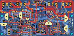
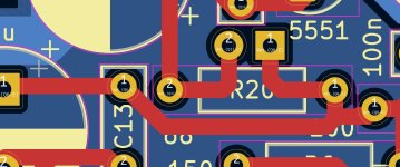
I made a little (last) change. Transistor Q8 and capacitor C7 have moved a bit. The connection to the bias transistor 669 get shorter. Some resistors have moved a little bit to get space to make the changes possible. Give me more days and i will find more to change... 🙂 (no only a joke)
Hennady, thanks for your look. I will make the gerber zip file and give a notice.
Peter
Hennady, thanks for your look. I will make the gerber zip file and give a notice.
Peter
Attachments
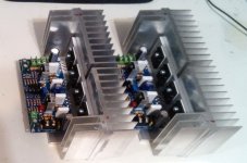
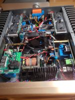
Upload zip file for testing..ok...pictures of test
You can get it now sending a pm to me. I have to wait until the kits arrive. Measurement in my amp is not easy enough. Perhaps the holes does not fit exactly to the old ones on the original pcb. If you never built a L20SE before it does not matter.
No guarantee, own risk. I have made the pcb as good as i could...
Peter
Attachments
![IMG_20240204_115804[1].jpg](/community/data/attachments/1176/1176845-28e8648004def155a135e99b1412690d.jpg?hash=KOhkgATe8V)
![IMG_20240204_115742[1].jpg](/community/data/attachments/1176/1176847-ee173d4067e1cf4f81b8e19f639fe37c.jpg?hash=7hc9QGfhz0)
![IMG_20240204_115629[1].jpg](/community/data/attachments/1176/1176849-30191c68f571dc873989e0dba873b3ba.jpg?hash=MBkcaPVx3I)
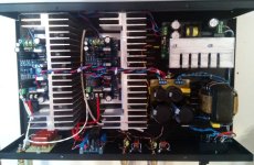
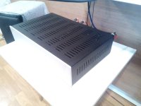
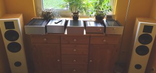
If I may, a few comments on the design.Pictures of my older L20SE
* when using a switching power supply, it is necessary to ground both the mains supply and the output.
*RCA input terminals must be located nearby in the housing so as not to create a grounding loop between separated inputs,
*in the case of one power supply for two channels, resistors in the input wire need 10 ohm resistors to break the circuit, while at the input terminals GND must be grounded to the case in order to separate the contour gnd of external interconnect wires.
*It is advisable to additionally cover the pulse unit inside the housing with a shielding sheet and reduce the dissipation area of the HF transformer.
Attachments
@ crispycircuit
The amp has power, no question. In a shootout between L20.5 and the original L20SE, the SE will loose. The sound is a bit loveless, no brilliance.
I hope the Hennady Mod makes sounding much better as the original version. BTW Its not easy to top the L20.5 😉
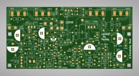
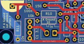
I had found a mistake on my pcb and fixed it. There was no input ground anymore because i deleted A Ground without putting a new Ground to the input. On the fixed pcb is an A Ground and a mark. "If A Ground is not needed short it". Everybody can choose now to use A Ground or even not...
Peter
The amp has power, no question. In a shootout between L20.5 and the original L20SE, the SE will loose. The sound is a bit loveless, no brilliance.
I hope the Hennady Mod makes sounding much better as the original version. BTW Its not easy to top the L20.5 😉
I had found a mistake on my pcb and fixed it. There was no input ground anymore because i deleted A Ground without putting a new Ground to the input. On the fixed pcb is an A Ground and a mark. "If A Ground is not needed short it". Everybody can choose now to use A Ground or even not...
Peter
Attachments
here I meant the output of a switching power supply.* when using a switching power supply, it is necessary to ground both the mains supply and the output.
All my amps running with SMPS without grounding exept the 0 voltage. Both pcbs and the negative speakeroutput have the same potential. RCA wiring is short as possible, away from AC voltage. Pcbs are away from AC. Rca is isolated to the housing, speakerterminals too... some little rules i know.
I have built about 180 amps, using boards from china. Months ago i found out to work with Kicad. Surely i never can design a amp, but if you give a schematic to me i make a pcb 😉
By designing a pcb perhaps i make some mistakes...i am thankful fo every tip i can get....learning as i wrote...
I have built ClassD amps too, using Hypex, Anaview/Abletec and Icepower boards, using frontends for last both. The grounding is more difficult. Icepower have PE on board, connected to the the board ground. Thats a little bit tricky to provide a groundloop.
In the later 80s i built a Elektor Mini Crescendo. One day thunder and lightnig outside. lightning comes in the house and my amp began to oscillate ....to that time no plan no internet..i trough it away...
Few years ago a built a new one, but the same problem. I had learned a bit more and i fixed it....thanks to the i-Net. Proud to fix it on my own...😊
But it is late..watch tv now an go to sleep...
Peter
I took my methodology for wiring the amplifier design from the design of pop guitar amplifiers, where the influence of interconnect wires is large, so there are features that I use in the manufacture of amplifiers, and also when my friends fail, by altering the wiring of other manufacturers)))All my amps running with SMPS without grounding exept the 0 voltage. Both pcbs and the negative speakeroutput have the same potential. RCA wiring is short as possible, away from AC voltage. Pcbs are away from AC.
Wow, after forty years of owning a soldering iron, I can hardly count that many,perhaps because I only make amplifiers for which I design the circuits myself.I have built about 180 amps, using boards from china.
Nicely done! How about adding an option to separate the VAS supply from the output/powerstage supply? You could include a jumper option for those that want to keep the supplies together.
In my experience adding a separate well made regulated supply to the VAS generally (I have not tested it on this amp yet) makes a big difference particularly when cranking things up a bit.
In my experience adding a separate well made regulated supply to the VAS generally (I have not tested it on this amp yet) makes a big difference particularly when cranking things up a bit.
@Hennady Kovalsky
Building amps with chinese boards or was easy to me. I always was searching for the best sounding amp. In my oppinion the L 20.5 is the best amp, designed by LJM. The next is the LJM L12-2. MX50X2 follows...the others designed by him.....mhmm, not my amps. Lukily i could sell most of the amps.
A few amps remaing at home...i have to begin with selling, no space at home for a few more...🙂
@A 8
Nice idea with setting jumpers for splitting the voltage. For the first time i read about a seperate power supply in threads about the old Elektor Mini Crescendo, splitting and using LM317/337 instead of the 3,9 volt zeners in the VAS, to get exacter voltage. My solution were 2 red matched red led.
I have never done before a voltage splitting. May be a try. Its a question of space in the amp. My cases are to small...🙂
Peter
Attachments
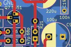
Put jumpers in...Kicad has no fitting jumpers in its libary. I took a led and changed the footprint. Kicad does not like that...😉🙁
Two variations are possible
Peter
Two variations are possible
Peter
Attachments
Last edited:
Yes. space is always an issue and the added transformers plus decoupling caps take the most space. A small 317/337 board or a simple zener regulated supply don't take that much space though.
I might at some point try using the main power-supply with 5-10 volts higher voltage than needed for the output stage and regulate the VAS to say 10 volts lower.
On the layout its a bit difficult to see where you made the "cut" but if you separate the supplies I think there should be a bit of local decoupling also for the VAS and/or outputstage and maybe the ground point for the (I assume) added VAS decoupling is important.
Hi A8,
i have not made a cut yet ore any changes. Only show a idea to get some jumpers in. I have to think it over. For the first time i will build the Hennady Mod and listen to the amp. Tuning may follow.
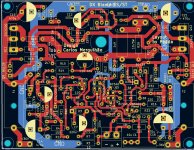
I have another project to complete. I want to build the Blame ST, designed by DestroyerX, Carlos, here in the forum years ago. The MKII Supercharged is very interesting too.
Similar to Apex FX8 and FH9 pcbs i designed a pcb for the Blame Amp. I hope it works...Pcbs are on their way, remaining at customs...
Peter
i have not made a cut yet ore any changes. Only show a idea to get some jumpers in. I have to think it over. For the first time i will build the Hennady Mod and listen to the amp. Tuning may follow.
I have another project to complete. I want to build the Blame ST, designed by DestroyerX, Carlos, here in the forum years ago. The MKII Supercharged is very interesting too.
Similar to Apex FX8 and FH9 pcbs i designed a pcb for the Blame Amp. I hope it works...Pcbs are on their way, remaining at customs...
Peter
Attachments
everything is very simple, you have just assessed the level of linearity of the input stages of the amplifiers you specified, the more linear the input stage, the more you like it, also indirectly everyone who participates in test comparisons on the input stages likes the linearity in amplifiers more.In my oppinion the L 20.5 is the best amp, designed by LJM. The next is the LJM L12-2. MX50X2 follows...the others designed by him.....mhmm, not my amps.
however, it’s sad to realize that we’re unlikely to see better topology options than what LJM currently offers.
Hi Peter, sounds like you have your hands full already 😎
If the Hennady mods clean up the the sound of the amp enough to my liking I may build a 4 channel bridged/balanced dual mono amp with separate and regulated VAS supply to be used for my surround and back speakers 🤔
If the Hennady mods clean up the the sound of the amp enough to my liking I may build a 4 channel bridged/balanced dual mono amp with separate and regulated VAS supply to be used for my surround and back speakers 🤔
I'll have to disappoint you, mods will bring the circuitry to life in terms of load characteristics, but for high sound quality I think this solution will not be enough.If the Hennady mods clean up the the sound of the amp enough to my liking I may build a 4 channel bridged/balanced dual mono amp with separate and regulated VAS supply to be used for my surround and back speakers 🤔
But Surround Sound Stage will work better with these mods.
Last edited:
- Home
- Amplifiers
- Solid State
- Power Amplifier LJM L20SE