Hi Tom,
no need to take a risk at the moment.
I looked back but could not find data on your proposal. Vrail=+-61Vdc, 5pairs of quasi output FETs (irf450?) Iq=150mA.
What else can you give me?
If you can keep the device case temperatures (Tc) below 50degC, then your 5pairs using guestimated FET data will easily drive a 2r5 resistive load continuously but the sink temperature will rise rapidly and case temp will only stay below 50degC for a short while.
I will need to do more accurate calculations before committing to a 2r0 resistive load.
ps. I have a copy of Bensen's spreadsheet for those that ask.
Hi Shawn,
I happy to hear the MJE340 was just a cold solder joint. So the pop you heard was from? I assume you just had to resolder the same MJE340 and all was well.
Excellent work on the case. I had a hunch things would be tight inside. I am not sure how much others realize how big that toroid you have is. I do, as I have a few 😉 I do not need as much power as you do, so my feeling is I will have four of quasi's modules per one of those toroids. I have not made a final decision on what MOSFET I will use, burt the APT4025BN, IRFP44x, IRF540N, IRF3415 are possible choices.
The case work despite the tight fit of toroid and your large PSU caps is still excellent. I only wish I had such talents to make a case. Of course I need to find the heatsinks first 😉 I am glad to hear Peckover's is still able to cater to the hobbiest as well. It has been some years since I was last there.
I am so happy to hear someone has Transmission Line speakers. I like to build a TL set of speakers, and then do a quickie dipole set to see what the difference is. Do you use TL subwoofers? Any special drivers for your TL's or speakers. I have some ribbon tweeters I am iching to use, but need a good midrange driver to handle to 6KHz before can crossover to ribbon.
Did I understand correctly that you are not using a soft start circuit with the amp at moment? If so how is it possible you do not have a circuit breaker tripping? The lights have to dime when you turn this on?
Do you plan to build another quasi amp with your other 44-0-44 926VA toroid?
I picked up two Dale 5 ohm 100W non-inductive resistors on weekend. Happened to see them while looking for some parts still. Thought be good to have pair for stereo amp testing.
Regards,
John L. Males
Willowdale, Ontario
Canada
11 July 2006 12:46
vodoochild_Ar80 said:
Thank Keypunch and don't worry i understood all (at least i thing so)
So just to be shure if i want to get 300W into 8ohm i would use something like a 75-0-75 (acording to quasi guide) 350VA trafo ??? its that right ?
vodoochild_Ar80,
Ok first I forgot to not all of the calculations I provided in Post #716:
http://www.diyaudio.com/forums/showthread.php?postid=957190#post957190
are for one channel. Sorry I forgot to mention that point.
I am not clear if you mean 75-0-75 rails or toroid. I will assume 75-0-75 rails. The calculations would be as follows:
75V**2 / 8ohms = 703.125 Watts P-P into 8 ohms
12 db down from 703.125 Watts = 703.125 / (2**4) = 703.125 / 16 = 43.9453 watts continous (very very deafing loud)
75V / sqrt(2) = 53.033VRMS
53.033VRMS**2 / 8ohms = 351.5625 Watts RMS (Music)
75V / 8ohms = 9.375 amps P-P
75V * 9.375amps = 703.125
53.033V / 8ohms = 6.629 amps
53.033V * 6.629amps = 351.562VA RMS
This is again assuming no losses and for one channel. For a transformer driving more than one channel you need to mutiply the number of channels to be driven by the VA rating of the calculations.
I would take the above formulas and work them out for 500VA 53-0-53 and 210W RMS and 360W RMS (RMS for 15 seconds I believe was what quasi meansured for) and you will have a sense of what losses you will experience vs no losses based calculations. I believe that the 500VA rating of the toroid quasi used actually limits the power the modules can deliver. I could be wrong in that assumption. So the deduced losses calculations may be greater than should be all elase being the same for quasi's amplifier. Just remember that the difference in db terms between 210W and 300W into 8 ohms is not that much. I would guess to be about 1.5 db. I also believe you cannot go to much highter in the rail voltage without the amplifier needing some redesign.
That all said and comments that 500VA for 300W mono musical amp makes perfect sense based on the calculations above. As I noted in my Post #716 the VA calculation should be based on the VRail. This VRail calculation would be the effective VRail the output devices see after losses. That means it will fall between the RMS and P-P based calculations. For a stereo version of the amp for your needs using the above calculations as a basis, quasi's ampplifier as an example to sue with the calculations of a real world example of losses and possible limit due to VA rating of the toroid used you will need at least 1000VA using at least a 60-0-60 transformer to allow for modest losses.
Also remember that an 8 ohm load is not purely resistive. I tend to use 4 ohms to calculate for an 8 ohms load. As you will see when you calculate this will quickly demonstrate how the VA rating of 500VA per channel is modest even for music signal using 8 ohm speakers.
Regards,
John L. Males
Willowdale, Ontario
Canada
11 July 2006 15:16
AndrewT said:Hi Key,
drain to source voltages vary with the signal.
It's a bit like adjusting the tap (faucet) to let out more/less water. Your hand is the input signal and as you oscillate back and forth the water flow changes, well your Fet behaves similarly, as you adjust the voltage on the gate the current flowing from drain to source changes. Look up the Id vs Vgs curves.
Hi Andrew,
Thanks for reply. I have been "digesting" the curves since your reply to see if I can deduce the relationships of voltages. The reason I asked the question was I am trying to understand the Ciss/Crss impacts in a general sense and to help me refine how I determine which devices may pose a loading issue for the amplifer driver stage. Knowing the IRFP450 specs helps a bit in the comparison to other output MOSFET choices. I thought by asking the question I could refine my understanding.
Regards,
John L. Males
Willowdale, Ontario
Canada
11 July 2006 15:27
Thanks Shawn, Andrew, keypunch and quasi
Yes Quasi After the succed of shawn with the 10 mosfet version i was thinking to do one for the same reason (im still on time to start again),
i don't know if my heatsink will work, guess it should be rally big (will post a pic of mine) .
IRPF450 must do fine or my i use something more robust?
And for the power supply if evrithing is fine with a pair of 20,000/100v Caps and 75-0-75 1000VA (its going to be a litle more VA just for good luck) i should run two of amps with no problems. ¿?
PD:Thanks to all in this forum for the help.
This is the bigest thing i ever build (the previus was a tda7294 gain clone of 50w) i hope this work at first time.
Im starting to make the 10 mosfet version pcb and the psu that as two pair of caps (thanks quasi), i will try to post some pics later
2 ohm load...I am confident
Don't worry about it. I have a scope and a generator and some large dummy load resistors to try it on. The folks will want some real world test figures, I figure. 🙂
Give me a few days. I'm very curious to know myself and I wil report back to everybody.
T, I would still like to know what you calculate.
Shawn.
I'll be gentle, no risk.AndrewT said:Hi Tom,
no need to take a risk at the moment.
You got it all, I think?I looked back but could not find data on your proposal. Vrail=+-61Vdc, 5pairs of quasi output FETs (irf450?) Iq=150mA.
What else can you give me?
I will need to do more accurate calculations before committing to a 2r0 resistive load.
Don't worry about it. I have a scope and a generator and some large dummy load resistors to try it on. The folks will want some real world test figures, I figure. 🙂
Give me a few days. I'm very curious to know myself and I wil report back to everybody.
T, I would still like to know what you calculate.
Shawn.
Detail And Power In One Big Amp
Correct, I did not replace any parts on any of my boards, both were golden from the get go. My error was drilling the hole slightly off from center and I wrecked one of the trails. The pop could be from my imagination, you know how it goes when first firing up a new circuit? 😕
I think two large work contracts are closing at the same time? I may not be around for many months? Who knows?
The bottom line
-------------------------------------
Quasi ROCKS and plays sweet on the low stuff too!!!!
Shawn.
keypunch said:Hi Shawn,
I happy to hear the MJE340 was just a cold solder joint. I assume you just had to resolder the same MJE340 and all was well. So the pop you heard was from?
Correct, I did not replace any parts on any of my boards, both were golden from the get go. My error was drilling the hole slightly off from center and I wrecked one of the trails. The pop could be from my imagination, you know how it goes when first firing up a new circuit? 😕
Peckover's just sold me the metal, Arunas(Auged) cut it for me including the heat sinks. I will not go back to any of those people. I strongly suggest you buy metal from ASA if here in Toronto and cut it yourself on a table saw. For me it was like cutting wood and I re-cut all the pieces as I was not satisfied with the quality. I'm not willing to pay big bucks either. I'm all DIY! That is why I am here. 😎 Still, I can't even believe I cut aluminum on a table saw and cleaned it up with a router? It is all because of people like quasi sharing their ideas and vision. JAH to to the DIY!Excellent work on the case. I only wish I had such talents to make a case. Of course I need to find the heatsinks first 😉 I am glad to hear Peckover's is still able to cater to the hobbiest as well.
Off topic so send me an email or point me to another thread. I have been building speakers for many years. I have some cute little drivers.I am so happy to hear someone has Transmission Line speakers...
I guess my lights are on another branch circuit but when I turned it on at the test table outlet, the lights dimmed. 😱
Did I understand correctly that you are not using a soft start circuit with the amp at moment? If so how is it possible you do not have a circuit breaker tripping? The lights have to dime when you turn this on?
Now that is the 64 thousand dollar question! I'm going to blow all your minds with my next amp and it will have quasi in it 😀 I have 3 more of those XFMRs and I just picked up two 800Va 40-0-40. I have ambitious plans but I need way more time. OMG ! I'm talking like keypunch! Dude, you know I'm gonna beat you to it...😉Do you plan to build another quasi amp with your other 44-0-44 926VA toroid?
I think two large work contracts are closing at the same time? I may not be around for many months? Who knows?
The bottom line
-------------------------------------
Quasi ROCKS and plays sweet on the low stuff too!!!!
Shawn.
Hi Tom,
Bensen's spreadsheet uses the following to plot a SOAR curve for an output stage.
Number of pairs output devices.
Type/model number of device.
Transformer open circuit voltage.
Transformer regulation,
Heatsink size.
Iq.
Capacitor smoothing bank.
Emitter resistors.
Projected heatsink temperature ( to suit the duty you expect to use).
Maximum and minimum load resistance.
Maximum projected load phase angle (45degrees to 60degrees).
Rth c-s of your chosen insulator/compound
Finally, a judgement from the user on whether to play safe and use DC values or to stretch the envelope and try 100mS or even 10mSec SOAR values.
Manual tesing will NOT permit anything shorter than DC values!!!
Supply your numbers and Bensen's spreadsheet does the calcs and plots the graphs (6 superimposed on a Vce vs ID grid)
Hi,
search for Bensen and display posts. about a year ago.
http://www.diyaudio.com/forums/showthread.php?postid=644996#post644996
I was criticised for posting the spreadsheet by a respected contributor and I have no intention of attracting any more flack!
Email me (no unsolicited mail from me) and I will send you a modified version for either FETs or BJTs or both, that does a bit more than the original posting.
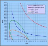
Shawn & 2 ohms
Here are the load lines for a reactive 2 ohm load with V & I 45deg out of phase and rails of +/- 61 volts DC.
It shows the SOAR of 5 IRFP450's derated for a case temperature of 50deg C.
Whilst the DC SOAR is inside the 2 ohm load line this should not present Shawn with any problems because;
1. The FETs are only loaded for about half the time per rail i.e, positive and negative swing (I know this is rough).
2. For music the 100mS and 10mS SOAR make more sense to me and whilst I don't know what the 100mS SOAR is (not shown in the databook) it's a safe bet that it's outside the 2 ohm load line.
3. The DC rails will sag (where have I heard that before) offering some protection.
So provided Shawn doesn't run a continous 10Hz signal at 3/4 power for several seconds everything will be ok.
Umm......If he did he and his speakers deserve what happens next.
Cheers
Attachments
Hi,
although Quasi has used a different method of calculation from Bensen, he has echoed my caution of using a 2ohm test load for a 5pair output stage.
I still need details if TomW wants corroboration.
although Quasi has used a different method of calculation from Bensen, he has echoed my caution of using a 2ohm test load for a 5pair output stage.
I still need details if TomW wants corroboration.
quasi,
I am trying to understand the jist of your wonderful SOAR graph.
1) Is it fair to say the graph is indicating 26 amps @ 2 ohms with I and V 45 degrees out of phase for 50 C temperature 20-30V, and about 18 amps at just above 60V?
2) Why would 5 pairs of IRFP450's at 100 C the IRFP450 lists continous Id of 8.7 amps (5 x 8.7 = 43.5 amps) total current capacity handling not be in SOAR for 50 C? I am not questioning your math, I am trying to learn more than my basic understanding.
Regards,
John L. Males
Willowdale, Ontario
Canada
12 July 2006 13:21
Hi Key,
I don't have a datasheet to hand but I'll try to guide you through it.
Go to the SOA graph that shows Id vs Vce.
Find the voltage that matches the Vrail i.e. 60Vce and look up to the DC and short term currents.
Now go to the temperature derating curve (straight line) and pull off the max power available at Tc=50degC.
Take the SOA current times Power@50C / Power@25C and you have the current available for a single device when Tc=50degC and Vce=60V.
The temp derating can also be found from the formula
Temp Derating Factor (DF)= [Tjmax-Tc] /[Tjmax-25] which for a 175degC device running @50C =0.833
If Tc=25degC the DF=1
Note that Tc=50degC requires the heatsink to be about 40degC and this gives a sink to ambient differential of about 15Cdeg depending on weather and latitude. An internal heatsink will tend to suffer from a higher ambient and need a bigger sink to maintain the same Tc.
Finally, the reason for choosing Vce=Vrail is that into a reactive load the maximum dissipation occurs within a few % of that voltage. Over the range Vce =Vrail +5% and -15% ie. 51Vce to 63Vce the device dissipation is close to actual maximum.
Andrew,
Thanks for the reply and directions. Your directions in the absense of a datasheet were just fine.
Darn, shoot. This results in less device power handing ability than the math I was doing (put in spreadsheet to make it easy to calculate) for number of different devices to screen them. I had been using the continuous Id 25C and 100 C datasheet values as the basis of my calculations. I just noticed that these Id values are specified at Vgs 10V (not sure what that means exactly, but suspect not what I assumed or outright ignored. Vgs is not Vds for sure.).
In concept here is what the calculations of the spreadsheet I created did to calculate if a device was within a SOAR and if so how many devices in parallel were required for the design transformer secondary voltage and Td:
1) Deduce Id derate from the datasheet listed Id 25C and 100C. I know it is not that simple, but with the other calculations I do and the other safety margins I have factored in it should offset more than any margin of error.).
2) Based on specified design Tc calculate Pd and Id based on the datasheet Pd specified derate and Id calculated derate.
3) Determine the expected Id based on the net VRail (VRail - any losses to VRail) and expected impedance load based on ohms law. I am aware there is a reactive element. I factor this in by designing for impedance load of half of the target load.
4) The spreadsheet then will hide other other calculated values like design Pd based on impedance, number of devices to handle the target power rating of the amp if either specified max Pd or Vdss exceeds calculated current needed from step 3 or Vrail is greater than Vdss plus safety margin.
5) Assuming the tests of 4 pass those respect device calculated values show with the Pd of the target impedance, target Id, and number of parallel devices required to handle the Id and/or Pd of the target amplifier load impedance.
Now the spreadsheet does a pile of other calculations that have nothing to do with SOAR/Power rating, but are there as I have entered the datasheet values of interest for the devices I was screening.
As an example, the results an IRFP450 would have the following results for 4 ohms resistive only load and 44-0-44 transformer for 170W amplifier:
Pd 70C 112.5W, 3 (3.02) Device Pairs
Pd 60C 127.5W, 3 (2.66) Device Pairs
As once can see the Pd 60C has a larger margin of safety assuming it never goes above 60C of course.
These calculations assume each IRFP450 device would handle 3 amps assuming current sharring was effective.
Refering to the IRFP450 datasheet SOAR graph as your procedure suggested shows no DC line sadly. The longest time listed on the SOAR is for 10ms which at 60V says the SOAR is 8 amps. I assume DC line on the SOAR graph is the continuous Id rating for Vds. So the Id 100C 8.7 amps (at Vgs 10V) continuous I had been using from the datasheet for my calculations was in error of understanding. The reason is my spreadsheet was saying that the SOAR Id wold be at least 8.7 amps per device, which based on your explaination is not the same as 8 amps for only 10ms from the IRFP450 SOAR graph.
I guess it is time for me to revisit all the devices I had in the spreadsheet and find a way to abstract the SOAR graphs to formulas and then do the calculations in the spreadsheet using the manner you had explained.
It is great you have explained this Andrew, as for over a year I have had the noted spreadsheet I created after much prior research on the internet and fourms for a few months to determine how to calculate the power (Id and Pd) of a MOSFET device.
Regards,
John L. Males
Willowdale, Ontario
Canada
12 July 2006 (15:20 -) 16:32
Hi Key,
go look at and read post750.
Now go and research the source/method that is referenced in the spreadsheet.
You will find that all the approximations and/or guesswork are not necessary. Once you have read the old article you will realise that your method has little basis in fact.
go look at and read post750.
Now go and research the source/method that is referenced in the spreadsheet.
You will find that all the approximations and/or guesswork are not necessary. Once you have read the old article you will realise that your method has little basis in fact.
Hi Andrew,
I had read Post #750:
http://www.diyaudio.com/forums/showthread.php?postid=960028#post960028
And the thread it pointed to. I downloaded the spreadsheet, but did not examine the cell formulas at all. I tried some values in the spreadsheet. It seemed sort of like the results I had, but maybe I was blind to see the similarities. I appeared less similar to the values I was expecting. I intend to eMail you for your variation of Benson's spreadsheet, but I need to house clean my inbox again after it again is flooded with more SPAM filling it up. In the meantime I will read the Benson thread more carefully and examine the formulas of the Benson spreadsheet more intently.
Regards,
John L. Males
Willowdale, Ontario
Canada
12 July 2006 17:20
Mr T, I will do my best:
Number of pairs output devices. 5 pair per channel
Type/model number of device.IRFP450
Transformer open circuit voltage. +/- 61VDC
Transformer regulation5%
Heatsink size. One half of one side of my amp would equal AAVID 82525 The amp is 6-3/4 inches high or 172mm
Iq. approx. 30 mA per device just as the Man suggested but my iq is 120 and after beers it is like 140 😉
Capacitor smoothing bank. 21,000uF per rail
Emitter resistors. 0.39 ohm
Projected heatsink temperature ( to suit the duty you expect to use). I have no Idea what the norm is here, how about cold, warm and hot?
Maximum and minimum load resistance. The usual suspects 2-8ohm
Maximum projected load phase angle (45degrees to 60degrees). I have no idea what this is but if you could fill it in and explain it to me?
Rth c-s of your chosen insulator/compound I used the gray colored “rubber” insulators with heat sink grease on both sides.
I checked out the XLS spread sheet, what was the big problem with it on the other thread back in the day? It looks nice.
Cheers,
Shawn.
Hi Key,
read the article that is referenced right at the top of Bensen's spreadsheet.
It explains all in easy to understand language. It also looks in detail at the mathematics needed and leads one through both driver and output device worked examples.
Once you have done your homework, then come back with your questions.
Hi Tomwaits,
the heat conformable insulators (the rubbery variety) do not need any heatsink compound.
I have seen references that adding compound reduces the performance of these insulators, but I cannot confirm that.
I'll get back shortly on the test load front.
What is the open circuit voltage of the transformer?
- Home
- Amplifiers
- Solid State
- Power amp under development