Hi Tomwaits,
using the irfp450 data and 44Vac transformer.
The 5pair will drive any 4 ohm speaker to 60degree phase angle when Tc<=50degC. and stay within the DC SOAR. In other words all day if the heatsink can maintain that Tc.
It will drive a 2ohm load to 30degree phase angle within the DC SOAR.
Taking a guess at a 100mS power limit of about 150%(=285W) of DC, since 10mS power limit is 500W or about 2.6times, this seems reasonable.
Using this 100mS power limit, as advocated by Quasi and others, then the 5pair can drive 2ohm to 60degree phase angle.
This indicates that the amp can conditionally drive any 2ohm speaker but you must not allow the Tc to exceed 50degC and the repetition rate for exceeding the DC levels should be relatively infrequent.
Domestic use and no distortion (onset of clipping) on transients should allow both conditions to be met.
For PA use big, possibly blown, sinks would allow 4ohm duty all night.
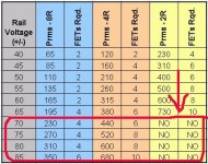
BTW. the sheet predicts power outputs of 200W into 8r, 350W into4r and 500W into 2r. Not quite three times into quarter load resistance but getting close. I use the three times & quarter as an indicator of a good PSU & output stage combination.
Finally, your smoothing cap choice only allows for 8ohm duty. The PSU ripple and RC time constants do not suit lower impedance loads.
edit:- I just increased the smoothing caps to +-45mF/channel and the 2ohm power came up to 600W. Now the drive voltage only drops 1.3db into quarter load. Go for it.
using the irfp450 data and 44Vac transformer.
The 5pair will drive any 4 ohm speaker to 60degree phase angle when Tc<=50degC. and stay within the DC SOAR. In other words all day if the heatsink can maintain that Tc.
It will drive a 2ohm load to 30degree phase angle within the DC SOAR.
Taking a guess at a 100mS power limit of about 150%(=285W) of DC, since 10mS power limit is 500W or about 2.6times, this seems reasonable.
Using this 100mS power limit, as advocated by Quasi and others, then the 5pair can drive 2ohm to 60degree phase angle.
This indicates that the amp can conditionally drive any 2ohm speaker but you must not allow the Tc to exceed 50degC and the repetition rate for exceeding the DC levels should be relatively infrequent.
Domestic use and no distortion (onset of clipping) on transients should allow both conditions to be met.
For PA use big, possibly blown, sinks would allow 4ohm duty all night.
BTW. the sheet predicts power outputs of 200W into 8r, 350W into4r and 500W into 2r. Not quite three times into quarter load resistance but getting close. I use the three times & quarter as an indicator of a good PSU & output stage combination.
Finally, your smoothing cap choice only allows for 8ohm duty. The PSU ripple and RC time constants do not suit lower impedance loads.
edit:- I just increased the smoothing caps to +-45mF/channel and the 2ohm power came up to 600W. Now the drive voltage only drops 1.3db into quarter load. Go for it.
ESP Articles of Possible Interest
While still trying to digest and researching to digest the SOA information Andrew suggested in concert with quasi's interesting SOA graph I stumbled across an article by Mitch Hodges, edited by Rod Elliot (ESP). There were a few interesting points that have been raised on emitter resistors and bias level chosen for the output MOSFET devices I thought be worth sharing.
The article is "Amplifier Design With HEXFETs - Getting good performance from vertical MOSFETs is possible":
http://sound.westhost.com/articles/hexfet.htm
Firstly the article, as does quasi, suggests 0R47 emitter resisters. I know the schematic shows 0R47, yet many want to and do use 0R33 (or even 0R22) instead. Well quasi you have solid support for 0R47!
The second point is a bit of a hot topic, pun intended. Though the article indicates the theory of what bias level you may need for a MOSFET device, it also states that this is generally to high for practical purposes. The reason I am highlighting this is not to suggest a higher bias than quasi has recommended for his design, though he does say a tad higher is ok with certain cautions. I would think the article suggests in Shawn's instance Shawn's ears may have heard something Shawn would of otherwise seen on a scope or from a THD output. Perhaps for some strange reason the more parallel output devices exaggerates some elements to require higher bias. Then again perhaps Shawn ears are a human THD measurement set? lol lol
I will skip the food chain of links that lead me to the above artice for HEXFET design, but where this started was the article that Rod Elliott (ESP) has written "Phase Angle Vs. Transistor Dissipation ":
http://sound.westhost.com/patd.htm
I think the article is informative.
To my surprise I discovered that there is a rational for choosing to design to half the desired impedance one wishes to have the amplifier handle. I will not say I am an audio design guru at all, I am still quite novice to much of the theory. I have no problem using math and formulas, so a little knowledge can be dangerous 😉 😉 🙂 This time my little knowledge had som basis in fact. It seems in a simple way that designing for half of the impedance one wishes to use the amplifier for is generally equal to a 45 out of phase angle of the load. No need to praise me. Even though I have known about Rod's site and various articles, this article I actually never read before, as I felt was beyond my ability to understand yet. I undestand a bit of it, but still have quite a ways to go. I can at least use the formulas during my lack of understanding and apply them as intended in the meantime. AKA more dangerous me!
As FYI to Andrew:
I am still trying to read and understand the articles you mentioned while using the IRFP450 datasheet information with Bensen's spreadsheet. This is going to take me a while to understand. I am sure there are some other elements of related theory I either do not know or have not undertstood yet to "understand" this phase angle stuff. In end I may not understand this as well as you are hoping I will be able to Andrew. I will keep working on it, just liek I still try to see if I can figure out some of the currents and voltage drops from the schematic with the currents and explaination of how to calcualte from quasi (the basics were easy, just losses that may have a varying voltage/current about the transistors and flows are bit beyond me still.)
I still find the Bensen spreadsheet more than a bit confusing even after reading the thread as well again. This is partly because I am used to writing spreadsheets that only require a data item be entered once, do the required calculations for much more of the data that is asked to be entered manually. The "output dev_" sheet is a mystry where the values it asks for are taken from (I understand the SOA chart just fine, just not what information is transfered to the spreadsheet). That said about the SOA sheet, I know how I would better program the "output dev_" sheet to link with the calculations sheet. The SOA sheet graph is a complete mystry.
I believe I will end up asking to have a copy of your modified version of the Bensen spreadsheet once I deal with my SPAM swamped eMail box again. Perhaps this will help me understand some aspects better with the clearer modifications you have made to the spreadsheet. As I noted previously the spreadsheet I created to do what was my attempt at ensuring I calcualted a safe design automatically blanks out devices that do not meet the design criteria for the power, Tc, load impedance, et al - for example too low Vdss or Id devices have their calculated values blanked to indicated out of specification for the intended design criteria. The same spreadsheet automatically determines the number of parallel devices required for the design qualified devices.
Regards,
John L. Males
Willowdale, Ontario
Canada
13 July 2006 (20:45 -) 22:40
AndrewT said:BTW. the sheet predicts power outputs of 200W into 8r, 350W into4r and 500W into 2r. Not quite three times into quarter load resistance but getting close. I use the three times & quarter as an indicator of a good PSU & output stage combination.
Finally, your smoothing cap choice only allows for 8ohm duty. The PSU ripple and RC time constants do not suit lower impedance loads.
edit:- I just increased the smoothing caps to +-45mF/channel and the 2ohm power came up to 600W. Now the drive voltage only drops 1.3db into quarter load. Go for it.
T, that is great stuff. Do you mean you increased the main cap bank to 45,000uF per rail to get the better result? I have dozzens of 10,000 63volt Nippon Chemi Con and if I remove the two big caps I can install at least 60,000uF per rail. Very close to the rail voltage but I fail to see any danger here. What are the general thoughts on those 63 volt caps?
Cheers,
SHawn.
TomWaits said:
T, that is great stuff. Do you mean you increased the main cap bank to 45,000uF per rail to get the better result?
Cheers,
SHawn.
Shawn,
If I may jump in here having used the Bensen spreadsheet and the reading I have done today.
The answer to the question is yes, Andrew is sugesting 45,000uF. Not only will you have a better result, you will have much longer life for the filter capacitors. The reason is less internal heating due to ripple currents. Not having the specs of your current filter capacitor, it is also possible with the lower impedances such as 2 and 4 ohms that those loads may exceed the ripple rating of your current filter capacitor (about 21,000uF I seem to recall) even though it is a Sprague.
As capacitance is increased, voltage rating a minor effect, the ripple capacity is small compared to the increace of capacitance. I happened to look at ripple ratings of capacitors earlier today based on research and reading I was doing today for the speaker load phase angle effect on load the amplifier sees. As typical examples of ripple current rating vs capacitance from one data sheet for same capacitor type:
63WV (RLQ):
uF/Amps
470/0.260
1,000/0.450
4,700/1.55
10,000/2.150
15,000/2.700
As you can see there are dimishing returns quickly in terms of ripple rating as the capacitance increases. It pays to parallel the PSU capacitors not just to reduce ESR, but you get more rippling handling at much less cost while also reducing ESR. When you you have capacitors in parallel the ripple demands are shared much like one parallels output drivers to share the current handing load.
One can extend the life of the capacitors a few orders of magitude with even a modest reduction of the ripple demand on the capacitor. Examples are a 5,000 hour 105C (RPX) rated life goes to 160,000 (18 years) by reducing the ripple demand by half (55C) of its rated ripple rating temperature, or a 5,000 hour 85C (RTX) rated life goes to 80,000 hours (9 years) at 45C.
Aside from the lower cost of using lower capacitances in parallel, you save on future replacement costs due to lifespan of the capacitors runnign at or beyond rated ripple rating.
Regards,
John L. Males
Willowdale, Ontario
Canada
14 July 2006 (00:00 -) 01:02
Re: More Caps
Hi Shawn,
Those capacitors will not be suitable for your amps based on the rails of your amp being +-61VDC.
You need to have at least capacitor rated higher than your rails. 75V would be fine, though 80V or 100V would be a better choice simply in terms of lifespan of the capacitor. Higher than 100V is of course great, but cost and size to fit into your amp woudl be the other considerations. As my last post suggested the ripple current rating though higher, will not be all that much higher for the size of the capacitor. Not to mention where will you fit this in your amplifier 😉
Regards,
John L. Males
Willowdale, Ontario
Canada
14 July 2006 01:09
TomWaits said:I have had these other caps around for a while:
Western Electric 75,000uF 60VDC
They are dying to get inside of an amp 🙂
Shawn.
Hi Shawn,
Those capacitors will not be suitable for your amps based on the rails of your amp being +-61VDC.
You need to have at least capacitor rated higher than your rails. 75V would be fine, though 80V or 100V would be a better choice simply in terms of lifespan of the capacitor. Higher than 100V is of course great, but cost and size to fit into your amp woudl be the other considerations. As my last post suggested the ripple current rating though higher, will not be all that much higher for the size of the capacitor. Not to mention where will you fit this in your amplifier 😉
Regards,
John L. Males
Willowdale, Ontario
Canada
14 July 2006 01:09
Hi Tomwaits,
It was obvious from the predicted ripple voltages when driving the lower impedance loads that the smoothing capacitors were far too small.
20mF can cope with 10Apk into the load. this equates to full power into 8ohms. Into 4ohms the drive voltage will be only 40Vpk (4r*10A) this is only 200W into 4r. If the peak current had been 12.25Apk then drive voltage = 49Vpk and max power is now 300W into 4r. So my recomendation is 25mF to 40mF for 4ohm loading and 50mF to 75mF for 2ohm loading.
Yes, that's what happens when you ask an amp to drive LOW impedance loads. I suspect your system would sound better if you put an individual amp on each driver rather than beefing up the amp for parallel loads.
The smaller capacitors will attempt to deliver the increased demand from the lower impedance loads and make an heroic effort at that, but just like the noble art of boxing, the smaller fighter wilts sooner. Yes, the voltage on the rail falls between charging pulses and the amp clips sooner. The output impedance also rises (I think?) due to the rail modulation and this makes the bass sound "soggy". It's all down to keeping the various compromises in balance.
yes, that was the only change in the model.Do you mean you increased the main cap bank to 45,000uF per rail to get the better result
It was obvious from the predicted ripple voltages when driving the lower impedance loads that the smoothing capacitors were far too small.
20mF can cope with 10Apk into the load. this equates to full power into 8ohms. Into 4ohms the drive voltage will be only 40Vpk (4r*10A) this is only 200W into 4r. If the peak current had been 12.25Apk then drive voltage = 49Vpk and max power is now 300W into 4r. So my recomendation is 25mF to 40mF for 4ohm loading and 50mF to 75mF for 2ohm loading.
Yes, that's what happens when you ask an amp to drive LOW impedance loads. I suspect your system would sound better if you put an individual amp on each driver rather than beefing up the amp for parallel loads.
The smaller capacitors will attempt to deliver the increased demand from the lower impedance loads and make an heroic effort at that, but just like the noble art of boxing, the smaller fighter wilts sooner. Yes, the voltage on the rail falls between charging pulses and the amp clips sooner. The output impedance also rises (I think?) due to the rail modulation and this makes the bass sound "soggy". It's all down to keeping the various compromises in balance.
quasi said:So provided Shawn doesn't run a continous 10Hz signal at 3/4 power for several seconds everything will be ok.
You kidding, me? Actually I ran 5Hz at 100% The amp laughed at me and said, “Son, is that all you got”….just kidding I did not do that but I may.😀
AndrewT said:Hi Tomwaits,
the heat conformable insulators (the rubbery variety) do not need any heatsink compound.
I have seen references that adding compound reduces the performance of these insulators, but I cannot confirm that.
That is an interesting subject and I have been in debate with it in the past. Is there a manufacturer guide stipulating this or are the application guides that show the use of SAID insulators without grease? I never did read much on the topic. Most certainly I want the thermal couple to be at its best. Also, what would you folks do?
keypunch said:… 160,000 (18 years)… (9 years) at 45C. you save on future replacement costs due to lifespan of the capacitors runnign at or beyond rated ripple rating.
Man you do play the long game. I smile thinking that I will still have these amps in 18 years and I’m cusin’ away in the shop cause the caps need replacing.
Cheers,
Shawn.
AndrewT said:
Using this 100mS power limit, as advocated by Quasi and others, then the 5pair can drive 2ohm to 60degree phase angle.
I suggest using the DC SOA at steady-state Tc, and using a single or double-pole filter to establish time-limited excursions of higher power.
Hi Mikeks,
Good suggestion. I like a more conservative approach.
Hi Shawn,
I would (and do) use mica insulators and heatsink grease. I am not a fan of some of the other "dry" insulators out there. I do tend to use a very thin film of heatsink grease on the dry types if I must use them.
-Chris
Good suggestion. I like a more conservative approach.
Hi Shawn,
I would (and do) use mica insulators and heatsink grease. I am not a fan of some of the other "dry" insulators out there. I do tend to use a very thin film of heatsink grease on the dry types if I must use them.
-Chris
Hi,
I'm pleased to see some corroboration of my recomendation to use DC SOAR.
Quite a few have suggested that my modelling, using DC values, is far too conservative.
I'm pleased to see some corroboration of my recomendation to use DC SOAR.
Quite a few have suggested that my modelling, using DC values, is far too conservative.
AndrewT said:Quite a few have suggested that my modelling, using DC values, is far too conservative.
On the contrary, DC SOA at steady state Tc (with thermal cutout to boot!) is the only foolproof way to ensure you still have a functioning amp. after prolonged, inadvertent exposure to a dead short.
Hi MikeS,
I have seen you post in some other forums and found them informative.
I have to agree with you, and quasi. Design to DC SOAR. Since I became aware my approach to calculate a SOAR rating was flawed about week or so ago, AndrewT's recent comments to Shawn, my recent postings, and the excellent modified Bensen spreadsheet I am still digesting I am now reviewing my prior calculations. I have to say it has been most enlighting including AndrewT noting a calculation that was so obvious and simple I never even thought of it. The formula has been most helpful.
I will suggest a variation to designing to DC SOAR. As example one could design a 3 ouput device pair wherein you design 2 pairs to DC SOAR and 1 pair to 100ms SOAR. For example, a device with DC SOAR at the Vrail has 5 amps, and same device has a 100ms SOAR of 10 amps. In this case the sum would be 20 amps. I know that the electrons will not use one pair of three at the 100ms SOAR and other two at DC SOAR. The point is one balances the very odd time a peak just barely needs to go above the design DC SOAR. This of course would be for amplifiers for home use that are in fact playing music that will have at least a 3bd (much more) peak above the RMS level. Given the dynamic and sparse peak nature of music what amounts to 1/3 above DC SOAR which I think for those that wish can use or there is an endearing device that would still then be useable.
I have a question that I am sure may have opinions, but I need solid facts for the answer. MOSFETs will not swing full rail to rail. That is given and the resaons/factors for are not subject of my question. As example using VRail of +-60 VDC and the net after losses the rails will only be able to swing +-50 VDC using the same PSU for both output devices and input/pre-driver/driver stages, what does one base the SOAR on, the rail before losses, after losses or some place inbetween? Would this same rail reference point be the basis for the VA and current calculations with respect to the "load"?
Regards,
John L. Males
Willowdale, Ontario
Canada
16 July 2006 19:01
16 July 2006 19:07 Corrected some TYPO errors. jlm
Hi Shawn,
As a quick guess from the hip .... Could be effective heatsink area.
Mind you, the gate charge issues with 10 + FETS might be getting hard to drive as well.
-Chris
As a quick guess from the hip .... Could be effective heatsink area.
Mind you, the gate charge issues with 10 + FETS might be getting hard to drive as well.
-Chris
AndrewT said:Hi Key, the device Vds or Vce.
Hi Andrew,
*I need to go to sleep, too much to do, not enough hours in a day*
Sorry Andrew, but is Vds or Vce inclusive or exclusive of the losses the devices will not swing +Vrail to -Vrail by? It would suggest to me that the answer in inclusive of losses as Vgs and Vce is what the load will see as the voltage swing. Then again, maybe there is something I am missing in my current understanding. (I have purposely ignored the fact a quasi (not the person ... lol lol ... then again maybe quasi is strickly a n-channel design 😉... sorry quasi I have been itching to find the right moment to say this) complementary design that this swing is not symetrical just to make it easy for the purposes of the question.)
Regards,
John L. Males
Willowdale, Ontario
Canada
17 July 2006 05:11
Re: Driving 2 ohms with higher Rails
I ran some SOAR models (that produced some of the SOAR & load curves I posted) for two ohm loads. With greater than 65 volt rails the load lines were too close to the 10mS SOAR for my liking. Even the output track on the PCB is too thin for this type of power. Into 4 ohms this amp will be rock steady with any of the recommended voltage rails.
Remember also that the intention for this amp (posted somewhere I forget) is to be used in a domestic (albeit very powerful) situation. If the amp is to be used into 2 ohms, please only at home. One more time.....This folks is a high quality Hi-Fi amp not a band or PA amp (although it could do a good job at moderate powers).
I did start another thread for a higher power (more efficient amp) but sadly my new job is very demanding and I have been dragged away. I will return to it ...someday.
Cheers
Quasi
TomWaits said:Why does Quasi not reccomend driving a 2 ohm load with rail supply higher than 65 volts?
Cheers,
Shawn.
I ran some SOAR models (that produced some of the SOAR & load curves I posted) for two ohm loads. With greater than 65 volt rails the load lines were too close to the 10mS SOAR for my liking. Even the output track on the PCB is too thin for this type of power. Into 4 ohms this amp will be rock steady with any of the recommended voltage rails.
Remember also that the intention for this amp (posted somewhere I forget) is to be used in a domestic (albeit very powerful) situation. If the amp is to be used into 2 ohms, please only at home. One more time.....This folks is a high quality Hi-Fi amp not a band or PA amp (although it could do a good job at moderate powers).
I did start another thread for a higher power (more efficient amp) but sadly my new job is very demanding and I have been dragged away. I will return to it ...someday.
Cheers
Quasi
mikeks said:
On the contrary, DC SOA at steady state Tc (with thermal cutout to boot!) is the only foolproof way to ensure you still have a functioning amp. after prolonged, inadvertent exposure to a dead short.
this amp does not have any active short cct protection. So even designing within the DC SOAR will not save it, not for a moment.
Cheers
Quasi
hey I'm on a role...so why stop.
Whilst some here consider my amplifier ratings to be not conservative enough we should ask the question ....
compared to what?.
Compared to most high quality commercially available amps my ratings can only be considered quite conservative. I own (and have owned) many of these commercial amps and have abused them often. It may not make sense but somehow they survived.
Ok...I'm done.
Cheers
Quasi
- Home
- Amplifiers
- Solid State
- Power amp under development