Hi Key,
I have never split open a transistor to find how it is made.
But I guess that the back face of a plastic packaged transistor will always hold the die.
The front of the die will have all the active (layered) elements and finally all the front and sides are enclosed in a non conductive plastic.
Now back to the back face, the metal die can be exposed or isolated. I would expect the isolated version to have a thin accurately controlled layer of bonded plastic.
The thermal characteristics of the front and rear faces of a plastic package will be completely different.
Try mounting an isolated package back to front, pass some serious power through it and prove me wrong.

Hi,
because you have listened and compared them or from studying the schematics?it's far superior to the Krell clone
ceramique may be the best HS compound
Made by Artic Silver
http://www.arcticsilver.com/ceramique.htm
Please read the specs and tell me what you think.
Made by Artic Silver
http://www.arcticsilver.com/ceramique.htm
Please read the specs and tell me what you think.
Hey Quasi,
I have a question for you. I have a power supply that will output around +-85 vdc, is that ok for the amp?
What about adding more output FETs, can the drivers handle the extra load?
Thanks
Lawrence
I have a question for you. I have a power supply that will output around +-85 vdc, is that ok for the amp?
What about adding more output FETs, can the drivers handle the extra load?
Thanks
Lawrence
lawbadman said:Hey Quasi,
I have a question for you. I have a power supply that will output around +-85 vdc, is that ok for the amp?
What about adding more output FETs, can the drivers handle the extra load?
Thanks
Lawrence
If you refer to the power selection guide you will see that the 10 FET board will handle up to +/- 85v rails and deliver about 350 watts into 8 ohms and 680 watts into 4 ohms (depending on power supply). This would really be the limit though and I have not tested the amp to these voltages.
The second and third stage transistors (MJE340/350's) will run very hot at these voltages and so a well mounted and large heatsink should be used plus a case fan to remove the warming air.
You could use more (or stronger) FETs but the gate capacitance will be significantly higher and the charging currents may be too much for the drivers. If you were prepared to re-design the PCB to make use of stronger driver transistors on large heatsinks then by all means you could use say 16 FETs.....(oh the humanity).
But maybe someone else has built a +/- 85 volt version. So whoever you are please share your experiences here with us.
Finally if you haven't got it send me an email and I'll send you a document with all the latest schematics, layouts, power selection chart and setup guide.
Cheers
quasi said:
If you refer to the power selection guide you will see that the 10 FET board will handle up to +/- 85v rails and deliver about 350 watts into 8 ohms and 680 watts into 4 ohms (depending on power supply). This would really be the limit though and I have not tested the amp to these voltages.
The second and third stage transistors (MJE340/350's) will run very hot at these voltages and so a well mounted and large heatsink should be used plus a case fan to remove the warming air.
You could use more (or stronger) FETs but the gate capacitance will be significantly higher and the charging currents may be too much for the drivers. If you were prepared to re-design the PCB to make use of stronger driver transistors on large heatsinks then by all means you could use say 16 FETs.....(oh the humanity).
[snip]
quasi,
Although I have wanted to use lower rails than your design I had done some digging in my searching for alternate parts, partly as I looked for more local sources to purchase parts. I discovered the following possible alternates to the MJE340/350's:
MJE15032/MJE15033 250V, 8A, 50W, TO-220
MJE15034/MJE15035 350V, 4A, 50W, TO-220
I do not think the:
MJE15028/MJE15029 at 120V, 8A, 50W, TO-220
MJE15030/MJE15031 at 160V, 8A, 50W, TO-220
have the needed voltage rating needed for even the +-75V Rails of your amplifier base design, but you will know this better than I will to say so one way or other.
The MJE340/MJE350 is 300V, 0.5A, 20W, TO-126.
In terms of the DC SOAR the MJE15028/29/30/31 appear close to the MJE340/350 and the MJE15034/5 appear to be much greater than the MJE340/350. The MJE15032/3 datasheet does not show a DC SOAR line, so it is hard to determine from the SOAR graph if at least as good as the MJE340/350, but I have this feeling in this case not as good as the MJE340/350.
It was not that I needed more power handling I would use the MJE15032/3 or MJE15034/5. My use of these would have been based on local availability while the TO-220 case/metal tab enabled better thermal transfer to a heatsink and less device stress with a higher device rating assuming the same heatsink was used as for the MJE340/350.
Correct me if I am wrong, but even with the use of the MJE15032-5 devices the device Tc heat to be disapaited would still be the same for a given rail voltage as the MJE340/350 would have?
I do not know if these MJE150XX devices above have a better, less or same ability to drive a larger capacitive or charging demand of higher rated MOSFET devices. I know on some otehr MOSFET N-Channel designs some builders have chosen to replace the BiPolar drivers with MOSFETS like IRF610, IRFP240, IFPP9140, IRFP140, et al. I clearly do not have the knowledge to know if it is ok to just replace the MJE340/350 with a higher rated MOSFET or not, let alone the sound quality difference this may or may not have. I simply mention as on some other N-Channel MOSFET designs the builder choose this approach or the designer used in the base design MOSFET rather than BiPolar drivers.
Regards,
John L. Males
Willowdale, Ontario
Canada
26 July 2006 (11:10 -) 11:55
Hi Hoangduongo,
From Post #797 -
http://www.diyaudio.com/forums/atta...tamp=1153579223
it seems that you had the wroing leg for Q4 (T4)-BC546. Should B be in the middle? You had it the same arrangement as the 2SC1845.
Hope I am helping.
From Post #797 -
http://www.diyaudio.com/forums/atta...tamp=1153579223
it seems that you had the wroing leg for Q4 (T4)-BC546. Should B be in the middle? You had it the same arrangement as the 2SC1845.
Hope I am helping.
To Quasi
For some reason I can't email or PM in this forum.
Do you have ..."a document with all the latest schematics, layouts, power selection chart and setup guide" posted in the forum or a website?
I would like to look at your project.Thanks
For some reason I can't email or PM in this forum.
Do you have ..."a document with all the latest schematics, layouts, power selection chart and setup guide" posted in the forum or a website?
I would like to look at your project.Thanks
Re: To Quasi
I dunno why you can't email me....maybe you're under moderation. This is applied to new members.
All the info you need is posted but it will be quite a search. Alternatively if you post your email address I'll email you the document.
I don't have a website .....yet.
Cheers
ppcblaster said:For some reason I can't email or PM in this forum.
Do you have ..."a document with all the latest schematics, layouts, power selection chart and setup guide" posted in the forum or a website?
I would like to look at your project.Thanks
I dunno why you can't email me....maybe you're under moderation. This is applied to new members.
All the info you need is posted but it will be quite a search. Alternatively if you post your email address I'll email you the document.
I don't have a website .....yet.
Cheers
Hi John,
All the transistors you mentioned are stronger when compared to the MJE340/350. It is sometimes difficult to follow the SOAR plots but my check revealed that they are stronger although the MJE340/350's stack up quite well.
I suspect the MJE340/350's are faster too (haven't checked).
Yes the amount of heat generated will be the same irrespective of the transistor used. The difference is though that a transistor with a higher rated dissipation will be generally be more reliable (not always) at higher temperatures. For the powers you are contemplating I wouldn't bother with anything else than the MJE340/350's.
Regarding FET driver stages.......sshhhhh here's a secret. I actually prefer transistors in audio amps because they are usually more linear. I use FETs in the output stage because of the power capability.
Cheers
Hi Quasi,
Check out the schematic of the Revox B-242. Mosfet drivers and bipolar outputs.
I PM'd ppcblaster with regard to his mail issue. It will resolve itself .......
-Chris
Check out the schematic of the Revox B-242. Mosfet drivers and bipolar outputs.
I PM'd ppcblaster with regard to his mail issue. It will resolve itself .......
-Chris
Hi Quasi,
I too was taken aback by Key's statement
It turns out that at elevated voltages i.e. Vrails of +-80Vdc and higher that the tiny MJE340 do indeed have a better current ability.
Only the MJE15034/35 can do better, but again at an even higher voltage the 340 wins out.
Where can you find fT info on the old 340 and 140 series transistors?
I too was taken aback by Key's statement
and almost jumped in with both feet, but the puddle was a bit deeper than I thought.but I have this feeling in this case not as good as the MJE340/350.
It turns out that at elevated voltages i.e. Vrails of +-80Vdc and higher that the tiny MJE340 do indeed have a better current ability.
Only the MJE15034/35 can do better, but again at an even higher voltage the 340 wins out.
Where can you find fT info on the old 340 and 140 series transistors?
Hi Anatech,
which bit of ONsemi's datasheet gives or alludes to fT information?
I have found two references to Philips and one other manufacturer that quote widely differing frequency information, but most datasheets are completely silent on this issue for these old style medium power transistors.
which bit of ONsemi's datasheet gives or alludes to fT information?
I have found two references to Philips and one other manufacturer that quote widely differing frequency information, but most datasheets are completely silent on this issue for these old style medium power transistors.
Doh....what nice transistors the MJE340/350's are. I shoulda checked closer....I only checked around the voltages Keypunch was gonna use....stupid quasi, stupid boy.
fT on a 340/350?? I just assume smaller transistor maybe faster transistor...stupid quasi....
Sigh
fT on a 340/350?? I just assume smaller transistor maybe faster transistor...stupid quasi....
Sigh
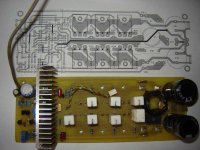
Hi guys.
I was too busy the last few days, so I can only test my amp yesterday. When I tested it, I have a prob: I couldn't set DC offset and bias current. No matter how I adjust VR1 and VR2, the DC offset and bias current varied all the time. The offset varied from 0mV to about +/- 150mV, and the bias current varied but had a alue only a few mV across the 100ohm res.
At first, I thought may be the mosfets were dead, therefore they draw no current, but surprisingly, when I connect a speaker( the Dc offset was not so high so I can connect a speaker without prob) and a signal to the amp module, it worked!It worked very powerful and quite quiet( there's still some hum, but I think it's normal).
I'm so confuse now, can you guy help me figure out what's wrong? Thanks.
And here are the pictures:
The amp module
Attachments
- Home
- Amplifiers
- Solid State
- Power amp under development