Hi Key,
I said
Maybe you should go to sleep earlier.
I said
there should be no ambiguity in that.device Vds or Vce
Maybe you should go to sleep earlier.
Uh oh ...embarrassed
Quasi make boo-boo.
The SOAR graph I attached in post #751 is incorrect. This chart is more accurate for a typical reactive 2 ohm load (61 volt rails 5 IRFP450's per rail).
It's worse than I thought but I would still be comfortable driving into 2 ohms in a domestic situation (big heatsinks).
Cheers
Quasi make boo-boo.
The SOAR graph I attached in post #751 is incorrect. This chart is more accurate for a typical reactive 2 ohm load (61 volt rails 5 IRFP450's per rail).
It's worse than I thought but I would still be comfortable driving into 2 ohms in a domestic situation (big heatsinks).
Cheers
Attachments

Hi guys, hi Quasi!
I'm building a Quasi amp, using Quasi' design(of course), but with a few changes:
- I redraw the PCB to fit my own needs, say redraw, but my design base much on Quasi's design
- I use MPSA92 for Q2/Q3, C2240 for Q1/Q4/Q5, KSE340/KSE350 for Q6...Q10, IRFP250N for Q11...Q16. I use these devices because I can't find the BCXXX series here, and the MJE340/MJE350 also, but I can buy the complementary pairs C2240/A970, MPSA42/MPSA92 and KSE340/KSE350 with a good price( the KSE340/350 is almost the same as the MJE340/350, but don't have the metal tab at their backs, I hope this won't cause much troubles)
- I also use 1N4007 for D1/D2, I think it will be safer.
- For C2/C3 I 390p caps, 33p for C4, 330n for C5/C6 and 470uF/200V for C11/C13.
- For R23...R28 I use 22 ohm(I can't find 27 ohm resistors)
I use 3 pairs IRFP250N for output devices, and the PSU is 55VAC( measured at no load). If you guys find any problem, please tell me as soon as possible, because I'm very curious and I can't wait to see how this amp works.
I also want to ask you some questions, please answer me:
- Where should I get the neg lead of the speaker: at the PSU filter caps, or at the poweramp PCB, I guess I should get it at the filter caps, am I right?
- How large the PSU caps should I use for this amp, are 20mF/100V or 20mF/80V caps OK?
- For the Zobel network, can I use 5ohm 5W res and 100n/250V cap? I can't find 10ohm 5W res that can stand because their leads are too short, and I have some good 100n/250V caps.
- How many turns should I wound for L1, I have 1mm enameled wire and 20mm dia bobbin.
At last, here is my redraw PCB, feel free to use and comment, the dimensions of the PCB is 200mm X 71mm and you should get the right values if you print the images at 600dpi. For more accurate, use can download Sprint Layout viewer(free) at http://www.abacom-online.de/uk/html/sprint-layout.html and print my original design file named Quasi.lay, but this file is compressed to .zip file due to its size and you will need to extract it before use, I hope this won't cause many problems.
Depend on the method you use to make PCB, you may need to use the mirror view of the track, so be careful!
If anyone have problem when drilling the heatsink because of the hole distance, please tell me and I will help if I can.
Sorry for my poor English.
Regards,
Duong.
Hi Hoang,
I have taught English professionally to Vietnamese speakers, and your written English is superb. I can't imagine why you are apologising for it - heck, if I wrote Vietnamese like you write English my head would be three feet across!!
The Quasi amp is a very good, stable, innovative design. I have met Con, the designer, and he impresses me greatly as knowing exactly what he is doing.
Cheers,
Hugh
Well, that's me name.....had to happen one day I s'pose.
Hi Hugh you have mail.
Cheers
PS. No problemo.
Hi Hugh you have mail.
Cheers
PS. No problemo.
Hi Hoangduongo
You can use the transistors you have just watch the pin-outs. If the KSE340/350's are isolated they may not have the same dissipation rating as the MJE's (I haven't checked) so you may want to use a bigger heatsink than I did. I like the heatsink Shawn used if that helps you.
All your capacitor substitutions are ok too.
There is no reason at all to use 1N4007's. The current through D1 & D2 is very very small so use the ones specified. They will offer better performance in terms of ripple rejection.
Using IRFP250's is ok too.
Use the 100v rated capacitors. 55 volts AC rectified will give you 77 volts DC and this is too close to the rating of 80v capacitors.
The Zobel network does not have to be accurate at all so your component choices here are ok too.
About 30 turns should be ok for L1.
Finally all ground wiring should run in a star with the main ground being in the centre. This includes the speaker ground, this should run directly to the main ground.
Your picture posting did not seem to work..
Cheers
Quasi
quasi said:Hi Hoangduongo
Your picture posting did not seem to work..
Quasi
Oh sorry, I thought I had posted the files, so here is the track view(600dpi):
Attachments
hoangduongo said:Sorry, I thought I had posted the pictures, so here is the layout:
Hi Hoangduongo,
Nice neat work. I've only had a brief look and I haven't checked all the tracks but it looks good.
I've noticed that the ground from the feedback capacitor is on the same track as the input ground and it shares this for a few centimetres. In my layout I run these as seperate tracks to a common "star". I am curious to see if it makes any difference.
Cheers
Quasi
Hi Hoangduongo,
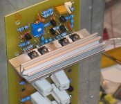
One more thing, what is holding the driver heatsink to the PCB. Your heatsink looks quite large and it might be too big to be held properly by the transistors.
Cheers
One more thing, what is holding the driver heatsink to the PCB. Your heatsink looks quite large and it might be too big to be held properly by the transistors.
Cheers
Quasi, thanks very much for your quick reply.
I will take care about the filter caps, because the 100V caps that I have are not as good as the 80V caps, but I think I will use 100V caps.
Your comment about D1, D2 is noted, I will replace the 4001s with the 4148s.
I haven't finished the board yet, but I will post pictures as soon as I can.
Again, thanks a lot for your help.
Regards,
Duong.
I will take care about the filter caps, because the 100V caps that I have are not as good as the 80V caps, but I think I will use 100V caps.
Your comment about D1, D2 is noted, I will replace the 4001s with the 4148s.
Actually I wanted to run the signal ground like you said, but unfortunately, my layout tenik is poor, so I couldn't.I've noticed that the ground from the feedback capacitor is on the same track as the input ground and it shares this for a few centimetres. In my layout I run these as seperate tracks to a common "star". I am curious to see if it makes any difference.
I haven't finished the board yet, but I will post pictures as soon as I can.
Again, thanks a lot for your help.
Regards,
Duong.
hoangduongo said:Actually I wanted to run the signal ground like you said, but unfortunately, my layout tenik is poor, so I couldn't.
I haven't finished the board yet, but I will post pictures as soon as I can.
Again, thanks a lot for your help.
Regards,
Duong.
Your layout looks good Duong. Good luck with the rest of your design and construction and please post some photos as you go.
Cheers
Oh Quasi, you are the fastest man I ever met
I have looked at the datasheet of MJE340 and KSE340, they have the same Pc: 20W, so I think it'll be OK.
And again, thanks very very much for your quick reply,Quasi,I hope you won't reply when I'm writing these words.😀
I have looked at the datasheet of MJE340 and KSE340, they have the same Pc: 20W, so I think it'll be OK.
Sadly, I forgot about it, but I think I can solve this problem. Actually, I may not use that big heatsink, I will take a look at the heatsinks i have, and choose the one that fit most, let's see.One more thing, what is holding the driver heatsink to the PCB. Your heatsink looks quite large and it might be too big to be held properly by the transistors.
And again, thanks very very much for your quick reply,Quasi,I hope you won't reply when I'm writing these words.😀
quasi said:Hi Hoangduongo
You can use the transistors you have just watch the pin-outs. If the KSE340/350's are isolated they may not have the same dissipation rating as the MJE's (I haven't checked) so you may want to use a bigger heatsink than I did. I like the heatsink Shawn used if that helps you.
[snip]
Your picture posting did not seem to work..
Cheers
Quasi
Quasi,
I have some KSE340/350 I just received this week. I am not sure if you have seen these or not. They look exacly like the Motorola/OnSemi TO-126 case except there is no metal about the rear area of the mounting hole. The KSE340/350 devices are all plastic, no metal and no "extra" isolation coating. This is different than many "isolated" devices (often TO-220 or a variation of TO-220) where the metal tabs appear to have a heavy coating that is the basis of isolation aspect of the device.
That said and the KSE340/350 being an all plastic TO-126 device, would it be reasonable to assume the KSE340/350 not requiring any thermal grease nor insulation pad net out to less thermal losses to a heatsink than a MJE340/350 TO-126 device having a small metal area about rear mounting hole that requires an insulation pad?
quasi said:
Hi Hoangduongo,
Nice neat work. I've only had a brief look and I haven't checked all the tracks but it looks good.
I've noticed that the ground from the feedback capacitor is on the same track as the input ground and it shares this for a few centimetres. In my layout I run these as seperate tracks to a common "star". I am curious to see if it makes any difference.
Cheers
Quasi
I have noticed another basic difference between the two PCB designs. In quasi's PCB design it appears that many of the tracks are laid out such that many are not parallel to each other. In contrast Duong's layout has many parallel tracks.
I happened to be reading about circuit layout choices a few days ago and all agree that parallel tracks have higher capacitance between parallel tracks (and wires or cables). Of course this has to do with "longer" tracks for which I will skip the definition of what "longer" is. Longer could realize a n impact to stability or an auidable difference. I will skip the pros and cons as that is a discussion all to itself that is beyond any knowledge to offer any sort of assessment on a case by case basis. Suffice to say some leverage this higher capacitance difference like it was a part of the circuit design not on the schematic to deal with certain aspects of the circuit proper. The question is (or may be not until Duong and other's try Doung's PCB) is if the parallel traces will have any impact over, beyond or instead of the interest quasi has in the difference to the star grounding approach of the tracks.
I am not trying to split hairs here. Just thought I mention in case is has some merit to consideration.
hoangduongo said:And the layout view(300dpi- I have to reduce the resolution 'cause the picture size is too large to post)
Doung,
I suspect the reason for the very large file size was because the layout image is mostly black. In fact when I viewed the image I just saw the component silk screen. The denser and blacker a image is overall the more space it will take up. When I used a graphics editing program I discovered a few things - the image was 72 dpi (not 300), it was colour based and there were only three colours. I only saw two colours - black and white.
I converted the .GIF image of in "quasi layout.zip":
http://www.diyaudio.com/forums/attachment.php?s=&postid=967052&stamp=1153579223
of post Post #790:
http://www.diyaudio.com/forums/showthread.php?postid=967052#post967052
to grey scale. To my surprise I found not just the silkscreen of he components, but the tracks in a light grey. I then inverted the image colours which turned the silkscreen of the components to black from white, the tracks (not visable in the original image) to a light grey and the black area to white. The white being most of the image space.
Oddly. for reasons I do not understand about .GIF, the saved .GIF file of he converted image was about the same size (tad smaller) as the original. Not what I was expecting as faxes that are blacker take much longer to transmit due to all the black in the page. This also results in a much larger fax image that is saved as file using any fax software. At least the image is much easier and informative (I hope) in this converted form. I then converted the image to .PNG just to see if the file size would be different. The .PNG file was about 2/3's the size of the .GIF files.
I have attached the resulting .PNG file for those that would like to see the difference in how the layout file looks and I suspect should look?
Doung, perhaps you can see if there are options in the software you are using for your PCB design to see if you wish/can create an image like I have attached. For sure if a file is colour it can take up more space. .GIFs have a unique manner of how they store an image. This means a colur vs grey scale .GIF may have little difference in file sizes. .GIFs are for sure far superior to JPGs for PCB images. PNGs are great too if the person converting from a different image format understands what the image formats are about and the specifics/application use of the original image.
Regards,
John L. Males
Willowdale, Ontario
Canada
22 July 2006 (11:30 -) 13:36
P.S. Darn, shoot I had to zip the .PNG. Seems the BBS software looks at the image file and decides it does not like images over 1000 X 1000 pixels. Errr, the file is only 47K, why should it matter? Zipping a compressed file like a .PNG or .GIF format only causes the resulting .ZIP file to be larger when zipping a compressed image format file such as .GIF or .PNG.
22 July 2006 (13:36 -) 13:48 John L. Males
Attachments
Hi Key,
If you want to dissipate some heat then you must use a thermal conduction medium between the sink and the back of the device.
Any air at the interface will increase the thermal resistance.
Eliminate the air.
since the back of the power transistor is plastic then an isolation (insulation) pad is not required.would it be reasonable to assume the KSE340/350 not requiring any thermal grease nor insulation pad
If you want to dissipate some heat then you must use a thermal conduction medium between the sink and the back of the device.
Any air at the interface will increase the thermal resistance.
Eliminate the air.
Hi Andrew,
Makes perfect sense to me. Some seem to argue using silcon grease increases the thermal reinterface to the heatsink. I would use the thermal grease even for plastic cases.
Just as an FYI, the KSE340/350 for some odd reason has a very fine pebbled rear of the TO-126 case, whereas the front of the case where the part number and Fairchild logo are laser inmrinted is very smooth. I know that heatsink material is not finished smooth. I would assume that given the unsmoth heatsink and the pebble rear of the KSE TO-126 devices when using sincon grease it would make little difference what face of the KSE faces the heatsink?
I think for these TO-126 KSE devices I would use Artic Silver or better as the thermal grease to provide the greatest thermal transfer given there is no real risk of shorting from the fine metal particles in Artic Silver.
Regards,
John L. Males
Willowdale, Ontario
Canada
22 July 2006 17:33
Driver Heat sinks
Quatro, you are a good man. I have made a pile of these heat sinks since the first set (I'm getting ready for multiple channels). If Duong is willing to buy me a coffee some day 🙂 , then I would be pleased to send him a few.
Sounds like Duong has it under control anyway.
Send me an email off list to receive your free "Quasi" driver heat sinks.
Shawn.
quasi said:... I like the heatsink Shawn used if that helps you.
Quatro, you are a good man. I have made a pile of these heat sinks since the first set (I'm getting ready for multiple channels). If Duong is willing to buy me a coffee some day 🙂 , then I would be pleased to send him a few.
Sounds like Duong has it under control anyway.
Send me an email off list to receive your free "Quasi" driver heat sinks.
Shawn.
Attachments
- Home
- Amplifiers
- Solid State
- Power amp under development