quasi said:Hi Shawn,
Did the MJE340 fry instantly or after a while etc.
Cheers
Quasi
Quatro,
It went fast. I think I heard it...sounded like a fuse popping? No visible damage.
Any insight would be good. I have a good board sitting right beside it so I "should" be able to sort it out.
Shawn.
TomWaits said:
Quatro,
It went fast. I think I heard it...sounded like a fuse popping? No visible damage.
Any insight would be good. I have a good board sitting right beside it so I "should" be able to sort it out.
Shawn.
Before you power up again, check for isolation between all transistors and output FETS from heatsinks. Also check for other damage to components feeding or being fed by the MJE transitors.
Check all the input and LTP transistors.
Also before powering up, measure the input resistance from ground to all rail connections, input & output and compare to the good board.
Good Luck
Quasi
quasi said:measure the input resistance from ground to all rail connections, input & output and compare to the good board.
I never did check it that way, very good. I'll be back after a few zzzzz. I can't touch it right now, I've had a couple drinks. 😀

Shawn.
Hi quiasi, im trying to get 250w - 300w into 8 ohms to use with my hammond piano so i coul use it for practice with my band ( and partys to!)
Thanks a lot Keypunch thast just the kind of answer i was looking for thanks.
I can`t wait to turn this on.
Thanks a lot Keypunch thast just the kind of answer i was looking for thanks.
I can`t wait to turn this on.
vodoochild_Ar80,
Your welcome. Sorry I did not notice some bad typo, not english, errors in the first paragraphs that I did not notice until earlier today. Seems when I poof read I need some lapsed time to not be so blind to my own typo errors. I also made a few sentances far too long. Sorry, I get into my thoughts and forget about good written grammer.
"I I may jump in here." should of been "May I jump in here."
and
"With respect to VA basically VA is the ampunt of Amps that the secondary part of the transformer can put out at the rated specs of primary input voltage and maximum temperature the transfer can run at. the VA rating is for the secondary and is not part of the rating of the primary voltage.?
should of been:
"With respect to VA basically VA is the amount of Amps that the secondary part of the transformer can output at the rated specs of primary input voltage and maximum temperature the transfer can run at. The VA rating is for the secondary and is not part of the rating of the primary voltage."
I am glad you found the information helpful, but most importantly understandable. I guess I am redeeming a very small bit myself for all those questions I asked 😉 *Hint, why there are so many "extra thread postings*
I may be asking you for some information in a different thread that I stumbled across an hour or so ago searching Google for a datasheet related to this project. I will likely post to that thread in a few days after I have had chance to read the long thread.
Regards,
John L. Males
Willowdale, Ontario
Canada
09 July 2006 17:11
09 July 2006 17:18 Opps, corrected yet again more typo's
Hi,
Speaking of questions I have another question. *small surprize*.
Is the drain to source voltage (for output MOSFETs) constant or varies as function of the input voltage? If constant, how does one calculate based on VRail. If varies, how does one calculate as function of the input voltage vs VRail?
Regards,
John L. Males
Willowdale, Ontario
Canada
09 July 2006 17:17
P.S. Shawn, I hope the cause of the MJE340 blowing did not cause too much co-latterial damage and the solution is not too painful. jlm
Hi Key,
drain to source voltages vary with the signal.
It's a bit like adjusting the tap (faucet) to let out more/less water. Your hand is the input signal and as you oscillate back and forth the water flow changes, well your Fet behaves similarly, as you adjust the voltage on the gate the current flowing from drain to source changes. Look up the Id vs Vgs curves.
10 MOSFET QUASI
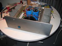
It is up and running and on the metro rack.
As it turns out the MJE340 was a cold solder joint/broken pcb trail. Nothing fried anywhere, which is very good.
As I type this I'm blasting the Moby record Hotel Ambient( love the 50Hz bass on the opening track). The 10 MOSFET QUASI is an extreme power house. I believe there is no compromise of sound quality reaching this power range. I can hear no sacrifice. I will need some time to listen to more music and I must finish this little set of speakers I have been working on for some time.
I have work to do yet. The case was so tight inside, I delayed the building of the DC output protection boards and the power supply boards, to make certain the pcbs I etch will fit. So in the end I will float the boards above the Toroid and I will make a small metal sheild to keep every one happy.
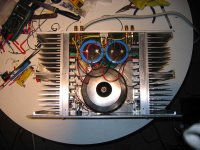
The blue LED I mounted in the front plate is toasted. Oops, I picked it out of the 3 I had in a bag fully knowing that I fried one of them last year
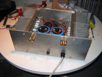
Then there is the placement of the speaker outputs and the input RCA's. I did it upside down and they are only 15mm apart, they look closer in the pic of the rear. The RCA is going to be a XLR in a little while so I will build a new rear plate when I have the time. I have lots of aluminum😉
The slow start circuit would be nice as the 1kVa xfmr pulls hard on the AC when turning it on. If I was rocking hard with it, I would make certain it had its own circuit breaker.
Shawn.
It is up and running and on the metro rack.
As it turns out the MJE340 was a cold solder joint/broken pcb trail. Nothing fried anywhere, which is very good.
As I type this I'm blasting the Moby record Hotel Ambient( love the 50Hz bass on the opening track). The 10 MOSFET QUASI is an extreme power house. I believe there is no compromise of sound quality reaching this power range. I can hear no sacrifice. I will need some time to listen to more music and I must finish this little set of speakers I have been working on for some time.
I have work to do yet. The case was so tight inside, I delayed the building of the DC output protection boards and the power supply boards, to make certain the pcbs I etch will fit. So in the end I will float the boards above the Toroid and I will make a small metal sheild to keep every one happy.
The blue LED I mounted in the front plate is toasted. Oops, I picked it out of the 3 I had in a bag fully knowing that I fried one of them last year
Then there is the placement of the speaker outputs and the input RCA's. I did it upside down and they are only 15mm apart, they look closer in the pic of the rear. The RCA is going to be a XLR in a little while so I will build a new rear plate when I have the time. I have lots of aluminum😉
The slow start circuit would be nice as the 1kVa xfmr pulls hard on the AC when turning it on. If I was rocking hard with it, I would make certain it had its own circuit breaker.
Shawn.
Attachments
I there
Nice to hear the 10 mosefet amp is working Shawn, that beast must be really laud(i guess you should be deaf by now), tell me what speakers you use?.
Thank Keypunch and don't worry i understood all (at least i thing so)
So just to be shure if i want to get 300W into 8ohm i would use something like a 75-0-75 (acording to quasi guide) 350VA trafo ??? its that right ?
Hi Voodoo,
375VA tranfo will let the Vrail sagg under heavy power.
The usual recommendation is VA=1.5 times maximum output power. The nearest is 500VA per channel. or 1000VA for a shared transformer in a multi-channel amplifier (not PA duty).
375VA tranfo will let the Vrail sagg under heavy power.
The usual recommendation is VA=1.5 times maximum output power. The nearest is 500VA per channel. or 1000VA for a shared transformer in a multi-channel amplifier (not PA duty).

vodoochild_Ar80 said:I there
Nice to hear the 10 mosefet amp is working Shawn, that beast must be really laud(i guess you should be deaf by now), tell me what speakers you use?.
Thank Keypunch and don't worry i understood all (at least i thing so)
So just to be shure if i want to get 300W into 8ohm i would use something like a 75-0-75 (acording to quasi guide) 350VA trafo ??? its that right ?
Hi Vodoochild,
Yes you will need a 500va transformer as a minimum to drive a mono 300 watt amp into 8 ohm, paticularly if it's going to be used for keyboards.
Also for musical instrument use, you should also build the 10 FET board or use stronger FETs if you build the 6 FET board.
Cheers
pejinm said:Very, very nice job!!!😉
Good work!!!
Thanks. I learned a lot doing this amp and I will continue to work on it so that it is fully set up right. I am very pleased with it and the sound is fantastic. I tried to use good quality board level components and I think things worked out very well.
vodoochild_Ar80 said:Nice to hear the 10 mosefet amp is working Shawn, that beast must be really laud(i guess you should be deaf by now), tell me what speakers you use?.
I have a set of 2 way DIY transmission lines and a 2 way reference set of DIY monitors. I honestly can not unfurl this amp at home or there would be destruction.
 I have this thing cranked for an hour or so and the heat sinks are cool to touch. 😀 It is obviously capable of driving a very low resistance!
Shawn.
Hi Tom,
Output stage durability depends on
1. Output load impedance.
2. Output stage temperature.
3. Vrail supply voltage.
4. Load impedance phase angle.
5. Time the stage is exposed to high dissipation.
6. Cycling effects that cause wide variations in output stage temperature, inducing fatigue in the die materials and/or die attachment to substrate.
does not necessarily follow.It is obviously capable of driving a very low resistance!
Output stage durability depends on
1. Output load impedance.
2. Output stage temperature.
3. Vrail supply voltage.
4. Load impedance phase angle.
5. Time the stage is exposed to high dissipation.
6. Cycling effects that cause wide variations in output stage temperature, inducing fatigue in the die materials and/or die attachment to substrate.
Cheers indeed!quasi said:A 10 FET Quasi is enough to make quasi jealous....
Anyway this calls for a celebration so here's cheers mate.
 Nice bottle opener 😉
 Thank you for sharing your time and your work with DIY
Shawn.
I guess I'll have to hook it up to a two ohm load and measure it? Then we'll have an idea 😉AndrewT said:Hi Tom, does not necessarily follow.
Shawn.
- Home
- Amplifiers
- Solid State
- Power amp under development