What kind of cap should be used on the RC output filter .068uF C12? 200V makes sense but what kind? I soldered MKT into the boards. Getting ready to test this out soon. Shawn.
Nice work Pejinm;
I like your arrangement of the heatsink tunnel and power supply. How does it all sound?
I'll check out the clipping indicator later today and give you my thoughts.
Good luck with the other parts of your project.
Cheers
I like your arrangement of the heatsink tunnel and power supply. How does it all sound?
I'll check out the clipping indicator later today and give you my thoughts.
Good luck with the other parts of your project.
Cheers
Re: Re: Re: Case options
Hi,
You can even stack the whole front plate with a second one, so the actual front plate mounting can be shared for both the front and support plates. 😉
I was of course only thinking of something like this. 😀
No, really, I didn't get that one... the more 'subtle' meaning of that word is new to me... Racist?
I'm of course not talking about the usual detergents. Some of those clean-it-all types are actually quite strong! I once got the skin on my fingers etched 'thin' and my throat and nose irritated really hard by simply cleaning the bathtub without goggles and gloves... !!! I guess with a little bit of heating something like "Bref" can etch PCBs 😉
You've been asking for stronger stuff, simple toilet bowl cleaners seem to be for those who can wait, then. 😉 😉 😉
Actually... it's computer science ... go figure 😀
But my recommendation really comes from experience: I in fact used to clean a set of wheels in a tub with that stuff. After the commercial wheel cleaner completely lost on them, I just grabbed the most 'pink' bottle of forbiddenly cheap cleaner and a brush... The wheels are still clean 😉
Cheers,
Sebastian.
Hi,
Yes, this may be the answer and it won't cost a nickle.
You can even stack the whole front plate with a second one, so the actual front plate mounting can be shared for both the front and support plates. 😉
"Beautiful screwheads" isn't that racist? 🙂
I was of course only thinking of something like this. 😀
No, really, I didn't get that one... the more 'subtle' meaning of that word is new to me... Racist?
I guess I should try these first, good thinking but I still love the idea of deadly chemicals with magical results.
I'm of course not talking about the usual detergents. Some of those clean-it-all types are actually quite strong! I once got the skin on my fingers etched 'thin' and my throat and nose irritated really hard by simply cleaning the bathtub without goggles and gloves... !!! I guess with a little bit of heating something like "Bref" can etch PCBs 😉
You've been asking for stronger stuff, simple toilet bowl cleaners seem to be for those who can wait, then. 😉 😉 😉
On that note I may pick up some spoke brushes. Thanks sek, you seem very practical, perhaps you're not a physicist like others in this place, whicuh is refreshing.
Actually... it's computer science
... go figure 😀But my recommendation really comes from experience: I in fact used to clean a set of wheels in a tub with that stuff. After the commercial wheel cleaner completely lost on them, I just grabbed the most 'pink' bottle of forbiddenly cheap cleaner and a brush... The wheels are still clean 😉
Cheers,
Sebastian.
Re: Nice work Pejinm;
HI Quasi,
Thanks for comments.
I'm very pleased with the sound of the amp, specially the bass and highs. It's very silent on the matter of noise.
What do you think about this clipp indicator schematic for quasi amp, I found it on professor Marshall Leach website. http://users.ece.gatech.edu/~mleach/lowtim/
Regards...
Miodrag Pejin
quasi said:I like your arrangement of the heatsink tunnel and power supply. How does it all sound?
I'll check out the clipping indicator later today and give you my thoughts.
Good luck with the other parts of your project.
Cheers
HI Quasi,
Thanks for comments.
I'm very pleased with the sound of the amp, specially the bass and highs. It's very silent on the matter of noise.
What do you think about this clipp indicator schematic for quasi amp, I found it on professor Marshall Leach website. http://users.ece.gatech.edu/~mleach/lowtim/
Regards...
Miodrag Pejin
Attachments
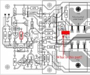
Quasi, what is the scoop on the unknown part in the layout image?
Also, is R9 33 or 39 ohms? I used 33's but does it matter?
And any further ideas or methods to push T8 into the heat sink? Chunk of plastic or foam wedged in there?
Shawn.
Also, is R9 33 or 39 ohms? I used 33's but does it matter?
And any further ideas or methods to push T8 into the heat sink? Chunk of plastic or foam wedged in there?
Shawn.
Hi Shawn,
The mystery component is a 0.1 uF poly or MKT capacitor.
33 ohms is cool there and won't make any difference.
Mounting T8;
Using the PCB (or printed layout) as a template, I marked and drilled a hole directly below T8's location. The hole should be big enough for a snug fit. Then I inserted T8 into the PCB from below, made sure it was straight and had enough lead length for the transistor body to go in the hole and bent the leads above the PCB. That done I lifted the board soldered only the centre lead and repeated the procedure. Once I was happy with the line up I carefully lifted the board without moving the transistor and soldered the remaining two leads. Then I put some heat-transfer compound into the hole and remounted the board.
This link shows a picture of the end result.
http://www.diyaudio.com/forums/showthread.php?postid=800468#post800468
Cheers
Mounting T8
That is crazy drilling a hole right in the heat sink! I love it. I have seen this done when servicing amps when I was a technician. Back reading I see someone used a different transistor and mounted it to the heat sink old school. What are your thoughts on this method and if it was the way to go what transistor would you use?
Also, is there any risk running the amp modules with out the heat sink to check and test before mounting them. I'm low priority over at the metal shop but his price is good so I should be patient. This will give me time to get the rest of it together. Can't wait
Shawn.
Sorry Shawn, can't run them at all without a heatsink. The FETs will heat up real fast and without the thermal feedback via the heatsink I givem about 10 seconds tops.
With respect to T8's mounting some constructors have gone for TO126 style transistors and mounted them with fly leads back to T8's location. A BD139 or similar is ok, just mount it close to the FETs and watch the pinouts.
Cheers
With respect to T8's mounting some constructors have gone for TO126 style transistors and mounted them with fly leads back to T8's location. A BD139 or similar is ok, just mount it close to the FETs and watch the pinouts.
Cheers
Hi Shawn,
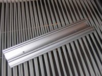
Very nice drivers heatsink. Is this a cut heatsink from one that had the fins on both sides?
I liked your earlier comments about placing the toroid at front of case in event it is rackmounted. Makes excellent sense that I have never seen mentioned as rational in all the postings and links I have read over past couple years.
Regards,
John L. Males
Willowdale, Ontario
Canada
18 June 2006 22:16
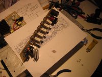
keypunch said:Very nice drivers heatsink. Is this a cut heatsink from one that had the fins on both sides?
Yes, see attached pic. I just cut them by hand with a hack saw and flipped them around the grinder for a minute or so. They are so light and with all four transistors bolted on, I don' think I'll worry about mounting it to the board. OMG Quasi will kill me
 Perhaps some brackets just in case.
keypunch said:I liked your earlier comments about placing the toroid at front of case in event it is rackmounted. Makes excellent sense that I have never seen mentioned as rational in all the postings and links I have read over past couple years.
It comes from experience as a DJ then working with live bands and now working with people in their recording studios. Amplifier size and weight has been scaled down so much over the years and big amps are hard to transport, carry and mount.
My Quasi may stay at home destroying my relationships with my neighbors but it may hit the street for some action. You never can tell.
Shawn.
Attachments
Hi Shawn,
Excellent. I thought this was the original heatsink before you cut it. I rather think quasi will not kill you for not mounting your driver heatsink on the PCB. On the flip side, seeing the care you are taking to make this amp robust for your use, you hindsight to mount on the PCB or some otehr physical form of securing the heatsink is likely a very good step to do. Besides you are patient 😉 while you wait for yoru case from the metal shop to return back to you 😉
Your DJ/Studio experience regarding the toroid mount placement will be one point I will take into account in amy amp I build. Thanks so much for sharing that practical real world experience.
As aside, a couple weeks ago I reformatted the Sayal parts of interest into a divided set of spreadsheets, and have been pricing things from them a few at time.
Did you go with the TO-92 or TO-126 case for the T8 Vbe?
I hope your case returns soon so you can fire up your modules to setup/test and then listen to them.
Regards,
John L. Males
Willowdale, Ontario
19 June 2006 01:52
We're on the late shift I see
I purchased the complete set of discrete components for a set of boards for under $20 from Honson. Fuse clips, stake-on connectors, driver heat sink, 330uFcaps were new surplus at Active for under $10. Power supply XFMR was Active $25. PWR supply caps $10ea at A1 surplus. My IRFP450s were gratus but they were $1.60 ea US at Arrow but I think they are going on allocation here in North America. Is this device end of life? Big ol pile of heat sinks was $50 at A1. ¼” aluminum from Peckover’s was $220. That's where I’m at right now.
I have a lot of Aluminum and heat sinks from these purchases to last a few projects so it will average out for less.
I still have to make the "mezzanine" boards with the safety circuit and I'm going to etch a power supply board with low voltage and mains in one. I morphed Quasi's PWR PCB artwork last night but I'm going to redraw it as it looks terrible.
I'm getting there and I should have lots more to post in the next few days.
Shawn.
Ha! That's a yes but no thing with me🙂keypunch said:Besides you are patient 😉
Sayal parts spreadsheet... [/B]
I purchased the complete set of discrete components for a set of boards for under $20 from Honson. Fuse clips, stake-on connectors, driver heat sink, 330uFcaps were new surplus at Active for under $10. Power supply XFMR was Active $25. PWR supply caps $10ea at A1 surplus. My IRFP450s were gratus but they were $1.60 ea US at Arrow but I think they are going on allocation here in North America. Is this device end of life? Big ol pile of heat sinks was $50 at A1. ¼” aluminum from Peckover’s was $220. That's where I’m at right now.
I have a lot of Aluminum and heat sinks from these purchases to last a few projects so it will average out for less.
I will use the TO-126 with the mounting hole, easier for me and Quasi says it’s ok. Still, I love the hidden T8.Did you go with the TO-92 or TO-126 case for the T8 Vbe? [/B]
Actually, I can’t wait. I purchased a tap and die set and I already mounted one of the boards to an extra slab of heat sink extrusion. It is good to get this practice in now because I snapped my first tap off in the hole! But I think I have a very good feel for it and I’ll be ready when the case comes through. I hope to have a set of boards tested and running ASAP
I hope your case returns soon so you can fire up your modules to setup/test and then listen to them. [/B]
I still have to make the "mezzanine" boards with the safety circuit and I'm going to etch a power supply board with low voltage and mains in one. I morphed Quasi's PWR PCB artwork last night but I'm going to redraw it as it looks terrible.
I'm getting there and I should have lots more to post in the next few days.
Shawn.
Hi Shawn,
Yes I am up late. My schedule is bit "off".
Most of my transistors I purchased from Supremetronic (now Honson). I really liked the APT4025BN, so I bought those (Stocked twice a year apart in small quanity) as my interested output devices. I also bought IRF740 and IRFP240 to experiment with as output devices and a few IRFP450's to use as quasi design reference output device to compare to the others. I also like the IRF530/540's. I have this neat idea to quick jig the output devices to compare them. From Electrosonic I bought some IRFP140's as I really like these, but they are so difficult to find locally. I bought all that Electrosonic had of these (25).
All but the 100uF electrolytics I have sourced from various surplus stores.
You of course know about the toroids I have sourced - I have six like you have in 44, and 40 V versions and 926 and 1127 VA ratings. In addition I have some of the ILP toroids two 15V 225VA with 4 secondaries each, two 25V 225VA and a 20V 225VA. The 15V ones will be for tweeter amps. The 20V and 25V will be my first toroids I will use to build my first quasi amp knowing quasi feels that these are too low voltage to use given the losses mosfet designs entail.
I have looked at bipolar designs as they have less PSU rail losses, but I have a basic issue with the extent of fake devices that are about for devices typically used as output devices. I have encountered many bipolar fakes in the city I am sad to say. I like the 2SC5200/2SA1943 devices, but so hard to find genuine. There are some excellent bipolar designs about such as ESP, or the Sysamp. I also read so many opinions of mosfet vs bipolar output device based amps which seem to suggest as much as there is a large following for bipolar, there seems to be a few minus aspects commonly expressed about bipolar. that said, quasi does have a bipolar n-channel varient of his design that interests me. My sense is generally the n-channel mosfet designs seem to favoured over the bipolar once all the information is distilled. The newer MJE OnSemi bipolar output devices seem not to be as well liked as the Toshiba versions. Even so there are some specific Toshiba devices that are very favoured.
Input filter caps, and other caps are well sourced from various surplus stores
The 100uF electrolytic, PSU filter caps in the 80-100V rating, heatsinks, relays are my next big challenge to source. I also need to source parts for softstart. The case(s) is the biggest and final challenge, but I will not concern myself about that until I have the quasi modules build and tested.
I am happy with my T8 alternative choices that are TO-126 case style. My challenge is enough MJE340/350's. My final build is for 28 amps for an active crossover based system.
I will first build a pair of quasi amp modules to be sure I have the elements I wish to change or add in down pat using the 20V toroid. Once that is down I will build four modules to run off one 44V 926VA toroid. This will be for passive based speakers. Once I have an active crossover build I will then start to build the rest of the amps I need. My power needs are modest even with passive based speakers, but for active based I will have lots of dynamic headroom, not to mention alot of cabling.
Why the bipolar varient from quasi interests me is the same basic input/driver stage design. I want all amps to be same design. Now if the mosfet power loss is not so bad with the 15V and 20/25V toroids, then I will make all amps based on the quasi mosfet design, but using targeted output devices for each of the W/M/T amps, for example the IRF740 looks ideal for a tweeter amp. My real ideal for tweeter amp is a IRF640N, but I cannot source these locally. I am hoping with the mid/tweeter using just a pair of output devices will reduce losses and offset the pentality of using a lower toroid secondary output rating.
So as you and other can see, I have an ambitious task ahead. It is partly why I have asked some of the questions I have. I want all modules to use same parts with excpetion of output devices, unless I can get my hands on more APT4025BN's, if I can all amps will be APT4025BNs. Right now the APT4025BNs or IRF540's will be for woofers, IRFP140's or IRF540's for mids, and IRF740's or IRF530's for tweeters.
Once a module pair is built I will be able to swap the output devices quickly to make listening and measurement comparisons. I expect these may prove interesting as well.
Regards,
John L. Males
Willowdale, Ontario
Canada
19 June 2006 04:27
keypunch said:My final build is for 28 amps for an active crossover based system.
I assume you are building a large PA for a theatre or concert hall? Or are you completely off the rails and doing this for home Hi-FI? Either way you'll need alot of this
 and some serious pile of time if you are on your own🙂 Now who said it, "go big or go home"?
Cheers,
Shawn.
Hi Shawn,
Strickly home active based system. 28 amps is based on 7.1 Home Theatre system 3 way active. When I first wanted to go active it was back in the Yamaha DSP-1/DSP 3000 days, so even then one needed 2 front stereo pairs (main and effects), centre channel, maybe a centre subwoofer (I am not a fan of mono subwoofer.), and stereo pair of rear effects. In theory I really need 34 amps to cover off 7.1 and DSP front effects to move forward to today from the basic 5.1 Home Theatre ! Me sane? Ask quasi if I am sane! =))
Most of my listening is music, so I am hoping I can get away with an initial start of 6 amps for front, 3 rear, and 3 to cover off centre channel and centre woofer to get the basic 5.1 Dolby and DSP/Stereo listening in active mode. For bare bones passive as I have now, I need 6 amps, which is typical of most basic Home Theatre currently. If you look at 10 years ago to now even the most novice average joe consumer has 6 amps, if not 8 to deal with 5.1/7.1, so to go active from basic stereo active that uses 6 amps to 28 is not really all that dramatic. For active I really do not need more than 120W/60W/15W for L/M/H active amps. Juice is not bad using Class AB amps. No way I do this class A, I would be fried to chrisp, not to mention broke on hydro costs!
I look forward to how your amp performs once you have it built. My calculations show with the 44V toroid you have, like me, power for 8 ohms will be anywhere from 120 - 170W, depending on losses which I have not been able to really estimate very well.
Regards,
John L. Males
Willowdale, Ontario
Canada
19 June 2006 16:44
Still, you may need a road map set with times lines and dead lines, without it, you may never get there. A modular approach would help and I bet you will modify your method once you got some amps and crossovers up and running. Now, get back to work. I'll bring the single malt over when your done. Battle of the amps!keypunch said:an initial start of 6 amps for front, 3 rear, and 3 to cover off...
WXN Says, "I guess Arunas is from Lithuania. No?"
I asked him today and he told me he was from Queen Street(major street in downtown core) 🙂 He has never been to the homeland. My metal work will be ready at the end of the week
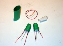
I made some better inductor/resistors today and wrapped them in 3/4" heatshrink and now they look bettern than the cat's XXX. The online java applet said 20AWG wrapped 20-21 times around 10mm core would give 4uH. Close enough, yes?
Shawn.
Attachments
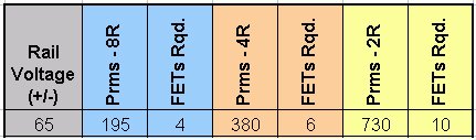
keypunch said:I look forward to how your amp performs once you have it built. My calculations show with the 44V toroid you have, like me, power for 8 ohms will be anywhere from 120 - 170W, depending on losses which I have not been able to really estimate very well./B]
How about this? The work has already been done.
Shawn
Attachments
Hi Shawn,
Thanks. I am aware of the table quasi made. I actually know the math behind the values to the table. The basic part of the math is fixed and repeatable. The various formulas I have to do the "same" calculation, result in different end power ratings. The reason for the wide difference of 120 - 170W is strickly a case of how much PSU rail loss there is. So on least rail loss side one has about 170W possible, but on low end with larger losses only about 120W for same 44V toroid.
For a 44V toroid rails would be at best 66.22VDC assuming no losses. The table suggests 195Wrms output indicating rail is 56.25 , ergo a loss of about 9V using the 65V rails. I think 9V rail loss is on very good side and likley to be more 12-13V loss for 8 ohom impedance. If you do the simple math approach, a 44V toroid would have rail net of 53.25 which translates into 37.65 Vrms = 177Wrms. These all assume a VA capacity that will not limit the voltage swing for the speaker/passive crossover load current demands.
I have created a set of spreadsheets using the different PSU calculations and embedded in it specs of various mosfets so I can see how many output devices for a given impedance I need for a given toroid with various loss voltages/factors while evaluating some of the other finer points of the mosfet device specs, such as combined Ciss.
Others can correct me if I am wrong, but the more output devices there are the larger the rail losses. One reason some like to build using only one pair of output devices, as well as no need for emitter resistors using one pair, is to keep rail losses to bare minimum. There are pros and cons sonic quality of using just one output device pair. Aside from the more parallel pairs adding to rail losses, the required emitter resistors add to the losses, in combination with bridge, filter capacitor and other PSU elements that vary with design or personal choices.
Regards,
John L. Males
Willowdale, Ontario
Canada
19 June 2006 19:40
- Home
- Amplifiers
- Solid State
- Power amp under development