Re: Hi JL. Re post #434
Quasi, is the setup guide too big for the fourm? If so then let me know. I like a copy and if you wish I will add to the pile of updates I need to do for the web site pages I have for the amp project. If the setup guide is larger than forum limits I suggest you send me the same whole package and I will validate the PCB varients updates I have made based on the thread comments since I first placed the site up. The site update effort is likely about a day's effort. The other 3+ days is to update various files and perhaps more if I need to resync from your base documents. Not to worry if I need to resync... just goes with the turf of the project.
Just a heads up in my review of thread again for JL I am at loss from one post you made after the last posting of the schematic:
Post #193
http://www.diyaudio.com/forums/showthread.php?postid=776203#post776203
"But you know, I just have looked at the schematic and have found a component value error. Resistor on the emitter of T6 should be 47 ohms not 22."
I have not been able to find this error on the schematic. I am using the schematics:
Post #166
http://www.diyaudio.com/forums/showthread.php?postid=601021#post601021
Attachment: nchan mos 350 1v4 schematic.pdf
http://www.diyaudio.com/forums/attachment.php?s=&postid=601021&stamp=1111237713
"The last schematic posted is slightly incorrect. R16 & R19 have been inserted. They exist on the PCB layout. "
--- AND ---
Post #325
http://www.diyaudio.com/forums/showthread.php?postid=818662#post818662
Attachment: nchan mos 350 schematic 1v4.pdf
http://www.diyaudio.com/forums/attachment.php?s=&postid=818662&stamp=1137491636
"I have attached the schematic again, this time with key current flows shown."
as the reference schematics, and so far seems Post #325 is same as Post #166 except with the additional noted current flows on former. Am I missing the error you posted regarding the value of the resister on emitter of T6?
Regards,
John L. Males
Willowdale, Ontario
Canada
13 April 2006 11:34
13 April 2006 11:39 Opps, small typo error I can see, sorry did not fix typos I cannot see 😉
quasi said:There is also a setup guide for the amplifier.
If anyone else would like this (it is too big to be allowed on the forum at about 300kb) drop me an email and I'll send it to you.
Cheers & Beers
Quasi
Quasi, is the setup guide too big for the fourm? If so then let me know. I like a copy and if you wish I will add to the pile of updates I need to do for the web site pages I have for the amp project. If the setup guide is larger than forum limits I suggest you send me the same whole package and I will validate the PCB varients updates I have made based on the thread comments since I first placed the site up. The site update effort is likely about a day's effort. The other 3+ days is to update various files and perhaps more if I need to resync from your base documents. Not to worry if I need to resync... just goes with the turf of the project.
Just a heads up in my review of thread again for JL I am at loss from one post you made after the last posting of the schematic:
Post #193
http://www.diyaudio.com/forums/showthread.php?postid=776203#post776203
"But you know, I just have looked at the schematic and have found a component value error. Resistor on the emitter of T6 should be 47 ohms not 22."
I have not been able to find this error on the schematic. I am using the schematics:
Post #166
http://www.diyaudio.com/forums/showthread.php?postid=601021#post601021
Attachment: nchan mos 350 1v4 schematic.pdf
http://www.diyaudio.com/forums/attachment.php?s=&postid=601021&stamp=1111237713
"The last schematic posted is slightly incorrect. R16 & R19 have been inserted. They exist on the PCB layout. "
--- AND ---
Post #325
http://www.diyaudio.com/forums/showthread.php?postid=818662#post818662
Attachment: nchan mos 350 schematic 1v4.pdf
http://www.diyaudio.com/forums/attachment.php?s=&postid=818662&stamp=1137491636
"I have attached the schematic again, this time with key current flows shown."
as the reference schematics, and so far seems Post #325 is same as Post #166 except with the additional noted current flows on former. Am I missing the error you posted regarding the value of the resister on emitter of T6?
Regards,
John L. Males
Willowdale, Ontario
Canada
13 April 2006 11:34
13 April 2006 11:39 Opps, small typo error I can see, sorry did not fix typos I cannot see 😉
Reply to post #440
Hi John,
1. Yes.
2. Yes. What I'm saying is that the noise threshold of the amp is so low that using BC550Cs will not produce an audible difference. But hey if you can get them (they're cheaper) and the rails are under 45 volts, use 'em.
3. Cool
5. What is of most importance is the SOAR of the transistor. Have a look at the SOAR chart and use the DC current v volts line. Compare this with the current flows shown in the schematic. With rails of 50v T6 & T7 will dissipate about 0.65 watts each. T9 & T10 will dissipate about 0.91 watts each. For rails under 50v you can use BF469/470.
6. Cool
8. The BC546 has no bearing on the output power or the voltage loss on the output stage. It only controls the idle current to stop the amp going into thermal runaway. Without it the output stage idle current will increase as the temperature increases until it destroys itself.
8. Can you send me a step diagram for the Quasi store dance?
Cheers
Re post #441
About post #193. This made reference to my other design in reply to a post by AKSA. Here is the link http://www.diyaudio.com/forums/showthread.php?postid=816432#post816432.
Cheers
About post #193. This made reference to my other design in reply to a post by AKSA. Here is the link http://www.diyaudio.com/forums/showthread.php?postid=816432#post816432.
Cheers
Re[03]: post #441
Hi Quasi,
Sorry I was not aware Post #193 as releated to AKSA's reference to the +-90V amp was of your other design.
BTW I only just found and read all of that thread few days ago. 😉 See I can keep quite and reuse answer to questions already asked *proud smile* lol lol lol I actually looked for that thread a few times over past year and could never find it for some unknown reason. Typical diyAudio search function complicated by general web search site (google, yahoo, dogpile, et al) results, well non results actually.
My appologoes for not being aware Post #193 was for the other thread schematic. At least I know I am not blind 😉
Regards,
John L. Males
Willowdale, Ontario
Canada
13 April 2006 21:07
Re: Reply to Post #440
Hi Quasi,
2) Interesting attribute of your amp. This clearly makes this design very special and wonderful.
5) Thanks for point re SOAR. After I do the initial screen of the basics of Vceo, Vcbo, Ic, Pd, I do look at the curves. I believe I am looking at the SOAR curves for sure as I know I need to dimension these like I dimension the output devices with respect to power handling vs temperatire vs current vs voltage. So thanks for noting and reminding me quasi. I need reminding as I sometimes forget this when looking at alternates for the MJE340/350's. Ideally I want to use the same set for all, not one pair of device type for T6/T7 and different type for T9/T10. The current flows have been most helpful for sure. I am still trying to figure out two comments you have made that affect the LTP branch that has me confused about how to do the calculations. I have found one program that may work as SPICE in Linux. I have yet to download and see if it will help me find the voltages I seem not be be able to correctly calculate at times. If I could calculate then I just make a spreadsheet of your amp and put in all the calculations myself so I can do a basic simulation for voltages, power and current. This would help me mostly for the finding alternates for the MJE devices of this amp. Finding alternates for all other devices has been very straight forward. I have found one possible source in the Netherlands for the MJE's, but have not inquirted if they are Mororola or Onsemi devices yet. I want no other as I believe Motorola, now Onsemi spin off, knows what the majic of these devices is that other companies making like device do not know about. In short the MJE340/MJE350 seem to be a "classic" much like many types of tubes now made by other companies to fill gap of the original company no longer around or making cannot identify so the new make old tube does not sound or perform like the original.
opps I made typo by listing 8 twice in row my orignal post... umm old age senility setting in I suspect. lol lol
8.1) Thanks for point re Vbe non-effect to amp losses. I made a conclusion with what I know so far. Clearly that was not a correct conclusion. Thanks for pointing out my error of conclusion/deduction.
8.2 ) As to "Can you send me a step diagram for the Quasi store dance?" I will try to find a close simulation of it via flash, automated gif/png, et al for you ok?
Regards,
John L. Males
Willowdale, Ontario
Canada
13 April 2006 21:36
13 April 2006 21:40 typo correction
I had an email requesting advice on how to solder and mount the output FETs.
I followed these steps.
1. Using the PCB as a template I drilled the heatsink then tapped the holes for the screws I used.
2. I temporarily bolted the FETs to the PCB with the legs bent back through the PCB solder pads, and once tightened I soldered the FET leads.
3. I removed the temporary bolts, then mounted the board (with FETs in place) to the heatsink using insulating pads and heatsink compound.
4. I checked for shorts from FET to heatsink.
I hope the picture does a better job explaining it.
Cheers
Attachments
Another error, sorry;
Hi folks,
There is an PCB track error in the 10 FET version of the amp module. A track from output FETs source and the associated 0.47 resistor is missing. This is corrected in the attached PDF.
Anyone who has already constructed this amp should solder a short wire link between the unconnected pads.
Thanks to Rolandong who pointed out this error.
Sorry & Cheers
Quasi
Attachments

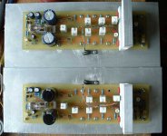

pejinm,
Excellent pictures and very neat work. I really like the size of the heatsink for the driver/pre-driver transistors. I have a some quick questions:
1) Is there a special reason the screw at the end for one of the PCB to heatsink mount since taking the pics? I noticed at DC end of one of the boards (one pic the predriver/driver heatsink is marked "1" in red on top of the driver/pre-driver heatsink). there is no mounting screw?) is not being used (or just not installed when pics taken as you were sooo excited).
2) It also looks like one output device (on the board with all 4 PCB mount screws on one pic where heatsink is marked "2" in one pic) does not have a screw to mount the output device to the main heatsink. There is a source resistor there, so am I correct there is an output device there and you were so excited to take the pics before you finished with installing the mounting screw for the output device?
3) Are you still using the MEJ340/MJE350 for pre-driver/drivers?
4) What transistor are you using for the Vbe (T8)? I see the T8 you are using is a TO-126 form factor. I wish to use a TO-126 for the modules I build and expect I will do as you did by running twisted wired from T8 to the PCB connection points for T8.
5) Is there a specific reason the Vbe (T8) is mounted on oppsite sides of the same middle output driver pair for your two modules?
6) It looks like the 4 TO-126's are insulated an thermally mounted using a silcon pad, correct? Is (T8) Vbe mounted as well using a silcon pad?
7) Aside from using a different device for T8 than the schematic, did you use any other different parts (transistors) or values (capacitors, resistors) than the schematic?
Again, excellent work pejinm.
I will be most interested in how warm/hot the pre-driver/driver heatsink of your modules are once you do some testing, stressing and listening of the modules. Why in part I ased if ther are any other different parts used questions above. I am partial to oversizing the heatsink as you have done. You have given me an additional type of heatsink that could be used for these four TO-126 devices.
I hope your modules do just fine in the initial power up and setting of the bias. Based on your careful and clean work so far I feel you should have no problems in powering up and setting up these modules for use.
I am still sourcing some parts before I can finailly dig in myself. I am way behind in making updates to the project web site I created. I also need to take a bit of time to modify the PCB to accept a larger physical size PSU module supply filter cap. I just happened to run into a DC circuit just by pure chance (as usual when not looking for protection circuits) that has LEDs for "Operating" and "DC" and want to see how easy it will be to add these to the DC protection circuit quasi used. I have a few ideas how this can be done.
I hope you enjoy quasi's design with many hours of enjoyable music.
Regards,
John L. Males
Willowdale, Ontario
Canada
06 May 2006 12:54
06 May 2006 13:08 Opps, lots of typo corrections, hope found all of them 😉
Hi John,
Thanks for your comments.
1) Hole drilling problems, I have't followed Quasis example from earlier post...
2)...
3) Yes.
4) I used BD139 becouse it's easier to mount (and maybe TO-126 case have a smaller termical resistance).I have't testeted the amp yet and I don't know how it will work...If someone have doubt in this please give some advice.
5) It's becouse heat is traveling upwards and it looks simetrical.
6) Yes, yes.
7) I used 12V relay I just changed the value of 470uF cap in dc detect to 100uF and the dc detect works fine (as Quasi sugested). Also I used 2SC2240 toshiba transistor instead 2SC1845 for T1 and T5.
Again thanks for your comments, and comments from the others are welcome too.
Regards
Miodrag Pejin😀
Hi Peninm,
Thanks for your answers.
From past postings of this thread, and many other projects on diyAudio I suspect the BD139 will work out fine for the (T8) Vbe. I agree with you the TO-126 will be easier to mount, and allow unmounting of board from heatsink if need be in future. I discovered the store where I can buy many of the small signal transistors had some TO-126 all plastic devices. Meaning there is no metal at rear of TO-126 near the mounting hole. That plus fact they never have any BD139's I checked out data sheets of what TO-126's they carried and I have narrowed down to a 2SC3502 and 2SC2911 for the Vbe. The former has all plastic case with no metal at all. I am likely going to use the 2SC3502 in hopes that by not needing a insulating layer of mica or silcone pad that the thermal tracking will have less thermal lag. I have no idea how to prove this, so I will just assume my theory makes sense. The only test I know I can run to at least make sure there is no thermal runaway is suggestion Eva made in different thread of running a sine or square wave at 50% P-P will stress am amp to its useable limits if designed and dimensioned well. I actually tried this on a recent commerical receiver I bought for $80.00 CND that has well dimensioned toroid and it stood up to the test. Scarey!!!1 lol lol Not many amps many hundreds of dollars more would, let alone a $80.00 CND receiver!
You clearly have thought out the reason why you mirror mounted the (T8) Vbe. It is obvious you want to ensure the left and right boards both have the module signal input at same end of the case. Hence the module boards will be flipped on their long axis to effect when mounted in the case. Smart thinking on the mirroring Vbe mount.
I like your comments about the 12V relay. I may be able to use the alternate values as well. I have some 44-0-44 toroids that have two secondaries, the second secondary is 12V. Your alternate parts for DC protection will give me a starting point for running the DC protection off the 12V secondary of the toroids I have.
I bought both the 2SC1845 and what little was left of the 2SC2240's at same store. I have the 2SC2240BL's the store carried. I had researched and many a good things said about the 2SC2240, not that the 2SC1845 had anything bad about it. So I decided to also buy the 2SC2240BL's to see if I can build a test module to do A/B comparisons. I will be very interested in your opinion of the sound and stability once your modules are broken in. I know we will not have quasi comparing to his modules, but hopefully have a good sense of any possible obvious, not so obvious or really no difference sound opinions.
Keep up your excellent thinking and work pejinm. I am sure quasi will be very interested in the sonic results as well as seeing your excellent building skills.
Regards,
John L. Males
Willowdale, Ontario
Canada
06 May 2006 16:08
Nice work Pejinm
_______________
Good to see your amp project well under way. Have you powered up any modules yet?
I hope you don't mind if I make some observations.
1. I noticed you are using a link instead of an output coill. That's cool. Think about using a thicker link though.
2. I can't tell if the two 22uf 50v capacitors in the DC detect section are bi-polar (non-polar) types. They might be, just can't see if they are from the photos.
Nice neat work. I look forward to seeing more pics.
Cheers & good luck
Quasi
Hi Quasi,
Thank you for your comments!
1)I have't test any of the amp modules, I need to build power supply and take care for some other things. I will put a coil later. I thought to use one from junked electronics but I did't find it.
2) Yes the caps are bi-polar 22uF.
I'm glad that you like my work. I will put more pictures as soon I progress with amp.
What do you think about BD139 in place of T8?
Will 2SC2240 work fine instead 2SC1845?
Regards,
Miodrag Pejin
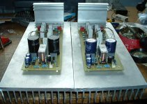
Nice work again Miodrag,
I like the ideas you have about the layout, particularly the mounting of the transformer between the heatsinks. The heatsinks will provide a degree of shielding.
I used a mains rated AC fan in my amp. I find these are quieter and can be slowed right down using a series high voltage capacitor. The fan in my amp is very quiet but still moves enough air around. I had trouble achieving a good result with a DC fan.
The 2SC2240 is a very good substitute and will give great results.
Cheers
Hi,
a couple of suggestions.
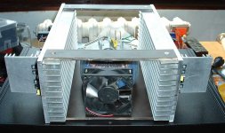
The fan could be doubled up, one to serve each channel. Then duct the sink fins from the fan to the exterior forming a tunnel exiting at the rear. It would be slightly easier to achieve if the fans were rotated 90 degrees.
Secondly, the driver sink is taking up a lot of case space. Could your extruded sinks, if heated, be bent in half to form a 90 degree angle? Alternatively, could the transistor legs be bent to allow the sink to sit alongside the PCB next to the input end i.e. flat side towards the PCB next to but above the components.
Finally, the suggestion that placing the transformer between the sinks and screening the active stages only works for electrical fields and then only if you complete the Faraday cage around the whole of each of the active sides. The case could be electrically tied into the sinks to form those two Faraday cages.
a couple of suggestions.
The fan could be doubled up, one to serve each channel. Then duct the sink fins from the fan to the exterior forming a tunnel exiting at the rear. It would be slightly easier to achieve if the fans were rotated 90 degrees.
Secondly, the driver sink is taking up a lot of case space. Could your extruded sinks, if heated, be bent in half to form a 90 degree angle? Alternatively, could the transistor legs be bent to allow the sink to sit alongside the PCB next to the input end i.e. flat side towards the PCB next to but above the components.
Finally, the suggestion that placing the transformer between the sinks and screening the active stages only works for electrical fields and then only if you complete the Faraday cage around the whole of each of the active sides. The case could be electrically tied into the sinks to form those two Faraday cages.
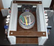
Hi Quasi and AndrewT,
Thank you for your observations.
Quasi:
You are right about the AC fan and I will probable use one like you do.
AndrewT:
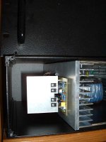
I'm not concern about the space in case. Here is the picture of amp in case, as you can see driver heatsink got good clearance. Also the Faraday cage is complete around amp module.
Thank you for your observations.
Quasi:
You are right about the AC fan and I will probable use one like you do.
AndrewT:
I'm not concern about the space in case. Here is the picture of amp in case, as you can see driver heatsink got good clearance. Also the Faraday cage is complete around amp module.
Attachments
- Home
- Amplifiers
- Solid State
- Power amp under development