I've read a lots of posts in this thread, but still need some help regarding MOSFET choice - is there any other property too be looked for except Vdss? For example, I could use any MOSFET which Vdss is rated more than rail voltage? The output power will be limited by device's Rds(on), but I can pick any NMOS, or not?
Also, what is maximum level of input signal it can handle without clipping? I can't get more than 1.1Vpp in simulation. Or it doesn't have a relation with output MOSFET choice?
Also, what is maximum level of input signal it can handle without clipping? I can't get more than 1.1Vpp in simulation. Or it doesn't have a relation with output MOSFET choice?
Last edited:
Hi FocusST225
Unfortunately with this type of failure it can be difficult to figure out what failed first. Did the faulty output take out the driver stage or did a faulty driver stage take out the output.
The good news is it cant get any worse. I would remove the faulty MOSFET (dont replace it yet) and replace R2. I would also replace C7 as it would have been stressed when output stage failed. Insert the setup resistors in place of the fuses - and run through the setup procedure. If everything is fine then you should be able to complete the setup procedure. You can run through the setup procedure without the MOSFET replaced. If you can't or if the setup resistors fail then we progress back into the amp.
Personally my next step would be to remove and check the both second stage transistors and also T4 the constant current source.
The gain resistor value change is to ensure the amp will reach full output with a resonable input of say 1.5v p-p.
Good luck
Q
PS. 90 volt rails really is the limit - maybe over. My other amp the ACTRK is stronger for this application.
I've read a lots of posts in this thread, but still need some help regarding MOSFET choice - is there any other property too be looked for except Vdss? For example, I could use any MOSFET which Vdss is rated more than rail voltage? The output power will be limited by device's Rds(on), but I can pick any NMOS, or not?
Also, what is maximum level of input signal it can handle without clipping? I can't get more than 1.1Vpp in simulation. Or it doesn't have a relation with output MOSFET choice?
Hi Rankot
The Rds(on) of the type of MOSFETs you need will have very little impact on the output level. Other Factors to consider are Vdss which must be more than twice the rail voltage and Ciss (input capacitance) - the lower the better although hard to find very low in power MOSFETs.
The maximum input level the amp will take befor clipping is dependant on the feedback network of R17 & R18. Reducing R17 reduces the gain with the gain ratio being R17/R18. Try this in the SIM first.
Cheers
Q
Thank You Quasi.
Found T10 was damaged. 2nd stage, T4 and C7 checked out fine. Replaced R2, T10 and damage Mosfet. Passed the setup procedure and module now working again. I suspect the output Mosfet failed creating the other issues. Thanks for the assistance.
Is it worth replacing R21 with LED or diodes for perhaps more stability?
Yes 90 volt rails are on the high side but the amp has run for 10 years with the only issue now from being overdriven.
The LED or 3 diode string is worthwhile but you will need to follow the setup procedure again. If it's a party amp then maybe not.Thank You Quasi.
Found T10 was damaged. 2nd stage, T4 and C7 checked out fine. Replaced R2, T10 and damage Mosfet. Passed the setup procedure and module now working again. I suspect the output Mosfet failed creating the other issues. Thanks for the assistance.
Is it worth replacing R21 with LED or diodes for perhaps more stability?
Yes 90 volt rails are on the high side but the amp has run for 10 years with the only issue now from being overdriven.
Glad the repair was successful.
Cheers
Q
Hi Quasi. Thanks. Why if party amp not to implement the LED or diode upgrade? My impression of the upgrade to create a constant 2V drop for more stability.
The main reasons for the LED or diodes is to improve clipping and crossover distortion as realised by some constructors. Whilst I haven't observed it the upgrade could also prevent other issues such as oscillation at clipping. Note I haven't done the diode upgrade. So maybe go for it. My earlier comment was related to the party amp running for 10 years problem free.Hi Quasi. Thanks. Why if party amp not to implement the LED or diode upgrade? My impression of the upgrade to create a constant 2V drop for more stability.
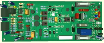
Quasis ACTRK 400/600 reborn
for Pro and domestic HI-FI
Op Front End
Balanced In,
Clip Limiter,
OCP Over Current portection
Crowbar DC Protection
Solid State Turn on delay / Fast off
Somebody interested to build ?
for Pro and domestic HI-FI
Op Front End
Balanced In,
Clip Limiter,
OCP Over Current portection
Crowbar DC Protection
Solid State Turn on delay / Fast off
Somebody interested to build ?
Attachments

Thanks Quasi. Noted. If it ain't broke don't poke. 😛The main reasons for the LED or diodes is to improve clipping and crossover distortion as realised by some constructors. Whilst I haven't observed it the upgrade could also prevent other issues such as oscillation at clipping. Note I haven't done the diode upgrade. So maybe go for it. My earlier comment was related to the party amp running for 10 years problem free.
Hello Quasi
greetings want to try ACTRK 400 is it ok to use on 55 volt DC +/- supply rails
WITHOUT the extra higher 10 volt dc supply. Can IRFP4227 mosfets be used.
warm regards
Andrew
greetings want to try ACTRK 400 is it ok to use on 55 volt DC +/- supply rails
WITHOUT the extra higher 10 volt dc supply. Can IRFP4227 mosfets be used.
warm regards
Andrew
1. For small power HI-FI IRFP4227 sure no problem
2. For PA Application 70 Volt DC use 2 pair FDA69N25 for Hi-Fi 55 Volt DC 1 pair FDA 69N25
3. WITHOUT the extra higher 10 volt dc supply you will NOT symmetrical clipping, dont care for Hi-FI ist important for PA high power
2. For PA Application 70 Volt DC use 2 pair FDA69N25 for Hi-Fi 55 Volt DC 1 pair FDA 69N25
3. WITHOUT the extra higher 10 volt dc supply you will NOT symmetrical clipping, dont care for Hi-FI ist important for PA high power
Hi AndrewHello Quasi
greetings want to try ACTRK 400 is it ok to use on 55 volt DC +/- supply rails
WITHOUT the extra higher 10 volt dc supply. Can IRFP4227 mosfets be used.
warm regards
Andrew
As Malta suggests you will not get symmetrical clipping without the 10v supply, will be about 3 to 4 volts short on the +ve swing. I have however built a version without the extra supply and it worked ok.
Pretty easy to get the extra 10v?
Cheers
In my amps I wound extra windings around the toroid transformer. I toyed with the idea of a voltage doubler off the existing winding and then passing through a regulator & filter. The front part of the amp that is fed off the higher voltage draws around 40mA so that could work, although I haven't tried it.How did you get extra volts - beside extra windings on the transformer?
I'm finalizing this, but need some more info which I can't easily find in a thread. I suppose output MOSFETs should be matched. Is it important to match if I use only two of them (IRFP260 for example)? If I use two pairs, which pairs should match and how? Shall I use this approach for low current https://www.diyaudio.com/community/threads/nelson-pass-easy-peasy-mosfet-vgs-measurement.299546/, or Nelson's high current matching?
Shall I match transistors of the input stage (BC556 / BC546), and driver transistors (BD139/140 and MJE340/350)?
Shall I match transistors of the input stage (BC556 / BC546), and driver transistors (BD139/140 and MJE340/350)?
Forget matching,
There are a number of suitable for audio mosfets FQA32n20c, IRFP 250 / 260 / 360 / 460
FQA40n25, FQA46n15, FDA69n25.
Usually for mosfet devices 1/3 of max power are sufficient for reliable operation, i use 2 couple of
FDA69N25 (TO3P package) @ +/- 70 volts into 4 ohm (rms sine wave) since 2 years with no
trouble in PA application, generous active heatsink is mandatory, in musical test they can handle
2 ohm load
mosfets will work for audio amplifiers, but ONLY if you use
a gate/drain snubber if you paralleling mosfets,
if you use only 1 pair for Hi-Fi you no need snubbers
Without the snubbers they WILL burst into oscillation and
destroy themselves quite quickly.
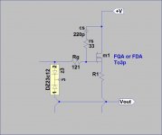
I suggest you use 1206 size smd components for Cs and Rs, and that you make the gate resistor
(Rg) a low power resistor (1/8 watt or 1206 or 1210) so that if the mosfet does decide to fail, the
gate resistor will quickly fail and save the rest of the circuit. Keep the track lengths between the
gate and the Rs and Rg resistors small (ie 5mm).
If you are using large mosfets, with 480W ratings, I would suggest 47R and 220p. This
is not particularly critical, but it's related to the nasty phenomenon and comes back to
the architecture of the die and the parasitics, particularly Ciss.
Most of the time there will be no oscillation without snubbers.
However, in a day, a week, a year, it will appear and destroy the device......
look sample
There are a number of suitable for audio mosfets FQA32n20c, IRFP 250 / 260 / 360 / 460
FQA40n25, FQA46n15, FDA69n25.
Usually for mosfet devices 1/3 of max power are sufficient for reliable operation, i use 2 couple of
FDA69N25 (TO3P package) @ +/- 70 volts into 4 ohm (rms sine wave) since 2 years with no
trouble in PA application, generous active heatsink is mandatory, in musical test they can handle
2 ohm load
mosfets will work for audio amplifiers, but ONLY if you use
a gate/drain snubber if you paralleling mosfets,
if you use only 1 pair for Hi-Fi you no need snubbers
Without the snubbers they WILL burst into oscillation and
destroy themselves quite quickly.
I suggest you use 1206 size smd components for Cs and Rs, and that you make the gate resistor
(Rg) a low power resistor (1/8 watt or 1206 or 1210) so that if the mosfet does decide to fail, the
gate resistor will quickly fail and save the rest of the circuit. Keep the track lengths between the
gate and the Rs and Rg resistors small (ie 5mm).
If you are using large mosfets, with 480W ratings, I would suggest 47R and 220p. This
is not particularly critical, but it's related to the nasty phenomenon and comes back to
the architecture of the die and the parasitics, particularly Ciss.
Most of the time there will be no oscillation without snubbers.
However, in a day, a week, a year, it will appear and destroy the device......
look sample
Attachments
I actually wanted to use only one pair of IRF510, since I don't need much power and I already have a PS with ±41V rails. But in case I need more power, I want to know how to match them, because I have 5 pairs. 🙂Forget matching,
There are a number of suitable for audio mosfets FQA32n20c, IRFP 250 / 260 / 360 / 460
FQA40n25, FQA46n15, FDA69n25.
Usually for mosfet devices 1/3 of max power are sufficient for reliable operation, i use 2 couple of
FDA69N25 (TO3P package) @ +/- 70 volts into 4 ohm (rms sine wave) since 2 years with no
trouble in PA application, generous active heatsink is mandatory, in musical test they can handle
2 ohm load
mosfets will work for audio amplifiers, but ONLY if you use
a gate/drain snubber if you paralleling mosfets,
if you use only 1 pair for Hi-Fi you no need snubbers
My MJE340 has hfe of 98, while MJE350 has 60. Is it acceptable?
IRF510 FOR CLASS AB - NO !I actually wanted to use only one pair of IRF510, since I don't need much power and I already have a PS with ±41V rails. But in case I need more power, I want to know how to match them, because I have 5 pairs. 🙂
My MJE340 has hfe of 98, while MJE350 has 60. Is it acceptable?
Power dissipation to low for Class AB
forget matching, ! you read to much Hi-Fi nonsense, for high power you need source resistor for paralleling
for more power > 100W Class D
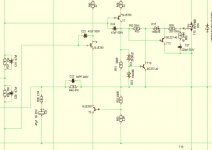
for schematic look postingHello Malta
greetings is it possible to share your schematic.
warm regards
Andrew
Its Quasi ACTRK 400/600 - Front end Input stage is replaced with OP amp and Balanced / XLR input with limiter
- Home
- Amplifiers
- Solid State
- Power amp under development