Using mosFETs for the output stage makes it very easy to decide how many are required to give reliable operation.
Maximum output power equals the Total dissipation of all the output devices divided by four (4).
If you have a +-50Vdc supply, then expect around 100W into 8ohms. That would require 400W of output devices.
If one decides to build for 4ohms duty, then the expected output would be just short of 200W. That would require 800W of output devices.
But to realise that target 4ohms power you will need to consider seriously where the current will come from and how you can deliver that current through the amplifier to the load. That is not easy. Many fail in this "current capability" and instead of getting close to 200W they end up with only 150W to 160W. In my book they have failed: 0 out of 10 !
Hi Andrew,
Thank you for your explanation, i use two 7A trafo, so does it mean it will be able to deliver for about 980VA which if my trafo has 70 percent of efficiency maybe it can be rated for about max 343W output/channel? If i take 60% from the max rated/channel, it would be safe to deliver 200W/channel using those trafo.
Am i correct for the calculation?
Thank you,
Roy
Transformers are typically between 90% and 97% efficient.
I don't know where you saw that a 7A transformer could be 70% efficient.
I don't know where you saw that a 7A transformer could be 70% efficient.
I think its not properly called efficiency, but in my place here many transformer are not truly rated, example: my 1A (36VA) transformer physic size is bigger than many 3A(108VA) with the same voltage output. Since im not sure how true my 7A transformer are rated, i take a number of 70% for safety reason.
Gooday,
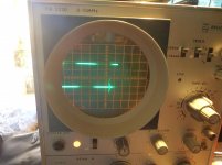
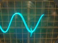
I have had problems with the amps which run OK when they get a low input signal and even does not sound bad on a speaker, but as soon as you increase the level then at some stage the bias starts to run away and the fets that self destructs causes the dog to jump. I have decided to put a scope on and and I find that there is oscillation on the output. On the square wave you can see it better. With or without load. Is there any advice how to cure this problem. With compensation caps ?
Help will be appreciated !
Attachments
This is the schematic?
http://www.diyaudio.com/forums/solid-state/43331-power-amp-under-development-79.html#post4252699
The output coil has a paralell R right? Value?
Output Zobel values? Type of resistor in zobel?
Just to try: changing C8 from 10pF to 22pF helps?
http://www.diyaudio.com/forums/solid-state/43331-power-amp-under-development-79.html#post4252699
The output coil has a paralell R right? Value?
Output Zobel values? Type of resistor in zobel?
Just to try: changing C8 from 10pF to 22pF helps?
Cortez, yes that is the schematic of the NMOS350. The resistor is a carbon compond of I think 2 ohm 5Watt and I think the coil around 3 uH. The ringing is also bad. I will increase c8 from 10 to 20 pf and see what happens.
Thanks
Thanks
Cortez, I have added another 10pf cap in parallel with C8, I cannot see a difference. The oscillation and ringing is still there.
And it is there with and without load in the same way and amplitude?
Does it change with the output level? Or with moving the cables? Chaning Iq of output devices?
Your zobel is then 10R + 68nF? Type of 10R?
Are those upper emitter resistors burned?
BTW: I'd cut off the OPS to test the IPS first wether it's present already there.
Does it change with the output level? Or with moving the cables? Chaning Iq of output devices?
Your zobel is then 10R + 68nF? Type of 10R?
Are those upper emitter resistors burned?
BTW: I'd cut off the OPS to test the IPS first wether it's present already there.
Cortez, the previous resistors burned when the bias ran away, but all components are new. I understand about removing the fets and see if the rubbish is coming from the frontend or the output stage. If I connect the scope directly before the zobel it is the same as well, so not the zobel causing it. With or without load, it is the same. I will remove the output tomorrow and see what happens. C5,6,9and 10 are 0.1uf 100V poly caps. Do they need to be a higher voltage, as the rails are 61 +-. Can this be a cause for oscillation ? If IRC C11/12 must be at least 160V caps.
Is there perhaps a minimum voltage for all ceramics ?
Is there perhaps a minimum voltage for all ceramics ?
Last edited:
And does this oscillation change with the output level? Or with moving the cables? Changing Iq of output devices?
BTW: did you make a general test after the burn? All resistors and semis are ok?
Iq-s and voltages are as they should be?
BTW: did you make a general test after the burn? All resistors and semis are ok?
Iq-s and voltages are as they should be?
Gooday all,
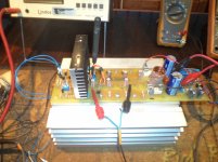
Seems I have got this bugger fixed. I had two problems. The first were the IRFP460 fets that I have used. Their capacitance is too high and they were second hand stuff. One out of three pairs would just blow up for no reason at all. They were recovered from ASM switchmode modules that are more than 30 years old and I think they were stressed. I replaced them with brand new IRFP250.With the other problem I drilled a small hole through the pcsb and mounted the vas transistor on top of one of the output fets. The bias is very stable this way. DC offset 0v and it sound good on the ear as well. Thought I just give some feedback, Now to fix the other channel and thanks for the people that helped. 🙂
Seems I have got this bugger fixed. I had two problems. The first were the IRFP460 fets that I have used. Their capacitance is too high and they were second hand stuff. One out of three pairs would just blow up for no reason at all. They were recovered from ASM switchmode modules that are more than 30 years old and I think they were stressed. I replaced them with brand new IRFP250.With the other problem I drilled a small hole through the pcsb and mounted the vas transistor on top of one of the output fets. The bias is very stable this way. DC offset 0v and it sound good on the ear as well. Thought I just give some feedback, Now to fix the other channel and thanks for the people that helped. 🙂
Just curious, what will be output power in 8ohms load if we use only 1pair of IRFP450? how much supply voltage use for it and any changes we need for 1pair of MOSFET?
the maximum output power is roughly the total dissipation of the output devices divided by 4.
1 pair of 190W devices will give ~100W
1 pair of 190W devices will give ~100W
Last edited:
Gooday, can someone plse confirm that this is ok. I don't want to damage working boards due to my stupidity. The Rail voltages are 61Vdc +- and the zeners will be 1watt 15v that will be added where shown to protect the fets. Feedback will be appreciated. The fets are IRFP250N devices.
Attachments
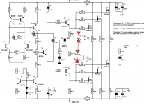
I think one zener plus a IN4148 per device is more usual. Placing the zeners on the output of the driver means the drivers are at risk of current overload if the zeners conduct heavily (overload duration etc dependent).
I think one zener plus a IN4148 per device is more usual. Placing the zeners on the output of the driver means the drivers are at risk of current overload if the zeners conduct heavily (overload duration etc dependent).
Maybe something like this?
Attachments

Maybe something like this?
Yes, but in Vrystaat's case the bottom zener/diode pair must be put in parallel with R22.
Yes, but in Vrystaat's case the bottom zener/diode pair must be put in parallel with R22.
Oh, I see: all N-mos.
- Home
- Amplifiers
- Solid State
- Power amp under development