In this case, I think you should post a complete wiring scheme so peolpe can help you in some way...
Regards,
Max.
Regards,
Max.
In this case, I think you should post a complete wiring scheme so peolpe can help you in some way...
Regards,
Max.
Thanks for the responce so far.
Managed to solve it. Bad input cap (C1). Replaced, and sounds back to normal.
Raj
Hi guys
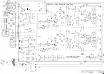
here latest schematic from my updated NMOS AMP
running @ 95V DC
compare to original version have add
Class H Stepdriver (not tested yet)
DC Protect Crowbar
VI Limiter and short circuit protection
Electronic turn on/off
Balanced input
cascoded VAS
any claims or improvements are welcome
here latest schematic from my updated NMOS AMP
running @ 95V DC
compare to original version have add
Class H Stepdriver (not tested yet)
DC Protect Crowbar
VI Limiter and short circuit protection
Electronic turn on/off
Balanced input
cascoded VAS
any claims or improvements are welcome
Attachments
Last edited:
Attachment: update
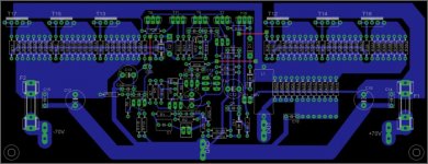
Class AB NMOS PCB Update
compare to NMOS MKII original version have add following features:
running @ 95V DC
DC Protect Crowbar
VI Limiter
short circuit protection
Electronic turn on/off
Balanced input
cascoded VAS
Overheat protection
any claims or improvements are welcome
Class AB NMOS PCB Update
compare to NMOS MKII original version have add following features:
running @ 95V DC
DC Protect Crowbar
VI Limiter
short circuit protection
Electronic turn on/off
Balanced input
cascoded VAS
Overheat protection
any claims or improvements are welcome
Attachments
Nice design whit class H step driver
Keep us posted on how it sounds
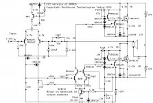
You might consider to add an input output comparator to reduce clipping
see here in this picture
I wanna implement this circuit in my NMOS350
ok but I dont have experience with this
and is it worth to spend time and add this ?
If you want assist me I will add in NMOS
normally today we dont need this in an amp because there are DSPs and Digital Crossover to prevent clipping
I think Behringer DCX 2496 can do this job better
Finally: how it sounds
great , hard to beat in sound from deep to the highs and rugged
Hi
i do not have experience whit this kind of protection but from what i understand this circuit compare the signal from input to output
If the signal goes to clipping in the output of amplifier this circuit automaticly reduce the signal from input until the sin wave from output becom normally
ok but I dont have experience with this
and is it worth to spend time and add this ?
If you want assist me I will add in NMOS
normally today we dont need this in an amp because there are DSPs and Digital Crossover to prevent clipping
I think Behringer DCX 2496 can do this job better
Finally: how it sounds
great , hard to beat in sound from deep to the highs and rugged
i do not have experience whit this kind of protection but from what i understand this circuit compare the signal from input to output
If the signal goes to clipping in the output of amplifier this circuit automaticly reduce the signal from input until the sin wave from output becom normally
.
Given this thread is called "Power amp under development", here is the next idea; Over-current protection.
This is just an idea for comment by the clever people who have help thus far.
The idea is to make a tiny board (under 1 inch square) that can be retrofitted to completed modules if desired. I decided on an opto-coupler approach to make the circuit universal.
One application is as shown; connected across the Vbe multiplier and shunting drive from the next stage during over-current conditions. Another application could be to use the optocoupler transistor to trigger some other safety system.
Anyway please comment and add what I missed.
Cheers
Q
As Beginner I need help for short circuit protection and VI Limit
who can help me and have values for for 85 V or 75 V DC @ 4 OHM
how to calculate values ?
"a diode in series with the optocouplers LED would make this threshold sharper."
Diode 1n4148 or zener ?
Attachments
As Beginner I need help for short circuit protection and VI Limit
who can help me and have values for for 85 V or 75 V DC @ 4 OHM
how to calculate values ?
"a diode in series with the optocouplers LED would make this threshold sharper."
Diode 1n4148 or zener ?
My guess would a 1N4148.
You need to sense the voltage drop across a resistor. This voltage must then be sent through a voltage divider that produces the voltage needed to turn on the LED inside the optocoupler when your current threshold is reached.
If your sensing resistor is 0.1 ohm and you want to light up at 10A, so as to speak, that is a voltage drop of 1V. If your diode turns on at 0.6V that gives you the ratio of 60%. 560 ohm and 820 ohm would do that.
820/(560+820) = 0.594
Does anybody have a SPICE model for the 4N25 or any other optocoupler? I like this idea and would like try it out.
Last edited:
My guess would a 1N4148.
You need to sense the voltage drop across a resistor. This voltage must then be sent through a voltage divider that produces the voltage needed to turn on the LED inside the optocoupler when your current threshold is reached.
If your sensing resistor is 0.1 ohm and you want to light up at 10A, so as to speak, that is a voltage drop of 1V. If your diode turns on at 0.6V that gives you the ratio of 60%. 560 ohm and 820 ohm would do that.
820/(560+820) = 0.594
Does anybody have a SPICE model for the 4N25 or any other optocoupler? I like this idea and would like try it out.
like this in schematic ?
D16 / D17 1N4148
R43/R44 and R49/R50 820/560 R
I dont understand calculation, sorry,.
Can you help me to calculate R43/R44 and R49/R50 if sensing resistor is 0,47 R and current treshold should be 10 A , 15 A and 20 A to turn on the LED inside the optocoupler
thanks for help
regards
Attachments
Shouldn't the diode in IC2 be connected to the same resistor? Like it is done for IC3. Also, shouldn't he base of the transistor be connected to something? Just asking...
For 10A through a resistance of 0.47 ohm the voltage drop is 4.7V. This comes from Ohm's law: R=V/I. Important stuff to know if one is building a big amp.
The datasheet for the 4N25 gives the forward voltage for the diode at 1.15V. The voltage divider should drop the 4.7V to this value. The current into the diode will be about 8mA (from the datasheet). This must be taken into account, as well as the voltage drop across D17.
The example in my previous post took no account of diode currents. Let's do it right this time.
We will make the current through R43 about 40mA (5 times the diode current) to make sure there's enough to go round. You could up this to 80mA. This will make the voltage divider calculation simpler because you can the ignore the LED current and just work out the values for the voltage divider as if it wasn't there. However, the max current for the 1N41418 is 200mA and this is a little close for long term comfort.
We'll stick to 40mA and plough on. The drop across D17 at this current is 0.9V (from its datasheet). The voltage across R43 must be 4.7 - 0.9 - 1.15 = 2.65V. The resistance is 2.65/0.04 = 66 ohm. We'll use 68 ohm, the closest standard value.
The current through R44 should be 40mA - 8mA = 32mA. The voltage across it is 1.15V. The resistance is 1.15/0.032 = 36 ohm. Use 39 ohm.
Can somebody confirm that I got it right?
With all this done, I'm not sure that shunting the Vbe multiplier will actually prevent any damage. All I can see is that the amp will go into class B mode, or am I missing something?
Last edited:
thanks for assistance, I want try to add to this great amp VI Limit to prevent any damage,.... hope it will work,
for Complementary BJT amps its easy to find working VI Limiter samples to add, but for NMOS Mosfet output stage hard to get quailified assistance
Im waiting for new SMPS with 2 Rails,.. want try to add 2 Step Class H in future
for Complementary BJT amps its easy to find working VI Limiter samples to add, but for NMOS Mosfet output stage hard to get quailified assistance
Im waiting for new SMPS with 2 Rails,.. want try to add 2 Step Class H in future
Last edited:
About output limiter...
...has anyone tried the flying catch diodes, as in Cordell's book pages 237 and 238?

...has anyone tried the flying catch diodes, as in Cordell's book pages 237 and 238?
actually have problem with my yesterday assembled NMOS 500
have about 12 - 14 V DC @ output but cant find fault,...
Rail is 80 V DC
have about 12 - 14 V DC @ output but cant find fault,...
Rail is 80 V DC
and maybe you got reason why adding these one,
please share
your mk3 schematic is faulty
use inproved working NMOS Design including DC Protect - Turn on Delay - input Limiter - Balanced Input.....thanks to apexaudio for assistance
look attachment
3 Diodes or 1 Amber LED (big improvement) are for symmetrical clipping and and sliglty more output power like ACTRK NMOS Amp
For 95 V DC you will need
10 pcs. IRFP460 or 2 pcs.APTM50UM13SAG or 1 pcs. APTM50AM38STG
assemble it t and enjoy
you dont need LP1 and LP2, D3 and D6 its additional for forthcoming Class H Stepdriver
Attachments
Last edited:
thanks nmos,
i diy my pcb please share this version in single sided,i will gladly built this i have a bunch of irf460 just please share 1 sided pcb,
thanks
i diy my pcb please share this version in single sided,i will gladly built this i have a bunch of irf460 just please share 1 sided pcb,
thanks
- Home
- Amplifiers
- Solid State
- Power amp under development