sir, i try what u told me last time but still its sounds like walkman using on 10'' woofer on full vol.
Hi greetings QUASI
what happened with NMOS MKII under development ?
Do you have finished final design with symmetrical clipping included cascoded second stage ?
I have build NMOS MKII under development and it works fine,... but have replace string of 3 1n4148 with 1 Amber LED
regards
I´m from PERÚ, and incredible more than 370 pages wow!!!😱😱 it is my interest of this amplo!! 😉 my mail is rbarriost@yahoo.com,: please I wana you last develope amplo; NMOS MKII 😀 ; fully esplantion please 😱, this is a great JOB!! congrats

Anyone selling selling PC boards for this amp?
Sam
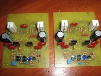
Yes i have PC Boards
Hi HMOS,
Can you post image with the boards you have?
How much for 2 boards shipped to london?
Cheers
Vlad 🙂
Can you post image with the boards you have?
How much for 2 boards shipped to london?
Cheers
Vlad 🙂
Hi HMOS,
Can you post image with the boards you have?
How much for 2 boards shipped to london?
Cheers
Vlad 🙂
Im sorry, I was a nice time but I do not longer build and support NMOS Amp
because
I habe now very much better sounding quasicomplementary BJT Design including all protections and relay free turn on delay, this design beat NMOS Amp,
its much clearer very transparent with imaging and depth so vivid you can “see” into the actual sound track. You’re going to hear every inner detail of the music the way the producer intended it to be heard and will playback any style of music in a Flawless manor.
I will share with Diy
So will the Nmos series serve PA audio applications?(I mean would this power amp be a good choice for amplifying vocals or musical instruments during live performance?)
Thanks in advance
Thanks in advance
use this files
remember if you use press and peel method first file is ok but if you use some other method you might need to mirror the file
Thanks alot Mr.maxente🙂
Im sorry, I was a nice time but I do not longer build and support NMOS Amp
because
I habe now very much better sounding quasicomplementary BJT Design including all protections and relay free turn on delay, this design beat NMOS Amp,
its much clearer very transparent with imaging and depth so vivid you can “see” into the actual sound track. You’re going to hear every inner detail of the music the way the producer intended it to be heard and will playback any style of music in a Flawless manor.
I will share with Diy
can u upload a image of this amp
NMOS200
Hi, everybody.
Prompt please: what standing current at NMOS200?
And that I bring together the amplifier, I do not know what current to expose.
Whether also it is possible to use condensers to 1000 pF on tension of 50 volts in case of a power +-35 volts? Or it is not enough?
PS If not so expressed I am sorry, I from Russia, know English badly, I use the translator.
PSS Yet up to the end completed, I look for angular heat sinks.
Attachments
You should read this:
????????? ?? Mosfet ? ???????? ???????? ?? ?? ?????? ???????????????? - ????? ?? ????????????????
Chuvak, idi a vegalab ili na cxem.net
????????? ?? Mosfet ? ???????? ???????? ?? ?? ?????? ???????????????? - ????? ?? ????????????????
Chuvak, idi a vegalab ili na cxem.net

I know you can't do anything about the link, but could you please post the rest in English. Thanks.
No problem.
I know you can't do anything about the link, but could you please post the rest in English. Thanks.
Constant current is about of 30 mA.Prompt please: what standing current at NMOS200?
Yes it is.Whether also it is possible to use condensers to 1000 pF...
Biasing amp
I am building the Quasi NMOS 500. I used .15 ohm resistors instead of the .47 ohm Quasi used as emitter resistors. In the construction guide Quasi states that the amp should be biased to 30 ma per output transistor.
5. If everything seems ok adjust VR2 to set the output stage bias current, by measuring the
voltage across the positive rail resistor. Adjust for a reading of 3 volts per output FET pair. I.e.
For a 6 FET board set for a voltage of 9 volts. This equates to a bias current of 30mA per
FET pair or 90 mA total. For a 10 FET board set for a voltage of 15 volts.
6. If everything seems ok, check the output offset voltage and adjust VR1 to achieve an offset of
less than 10 mV.
7. All being well switch off, back off the bias control trimmer (VR2) and replace the 100 ohm
resistors with 10 ohm 1 watt resistors. Switch on again and re-adjust VR2 to get 0.3 volts per
per FET pair across the positive rail 10 ohm resistor.
Is this final setup still correct even though I used .15 ohm resistors instead of the .47 ohm Quasi used?
Try using the same Vre value, i.e. 30mA across 0r47 = 14mVre
Using this value of Vre will result in ~100mA of output bias current per output pair.
This may be too much both for heat dissipation and to minimise crossover distortion, but it is a starting point to work from.
Using this value of Vre will result in ~100mA of output bias current per output pair.
This may be too much both for heat dissipation and to minimise crossover distortion, but it is a starting point to work from.
is there anyone out there try using ferrite beads at fets gate?
how to implement this which is directly connected to fets gate,is it the ferrite or gate resistor?
how to implement this which is directly connected to fets gate,is it the ferrite or gate resistor?
- Home
- Amplifiers
- Solid State
- Power amp under development