Re: Nmos200
Congratulations Malik123, Any pictures ?
Cheers
Q
malik123 said:Finally i made it😀
Sounds very clear and warm.Uses +-40v rails for now.
Quasi thank you for this project.Respect😉
Congratulations Malik123, Any pictures ?
Cheers
Q
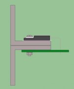
Vivek said:Hi Andrew, the angle is 2mm thick. Is that not enough?
You could always do this if you have plenty of 2mm angle. You will need to line them up and bolt them together perfectly though. Upside is you have a huge area of heat transfer onto the main heatsink.
Cheers
Q
Attachments
Re: Re: Nmos200
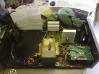
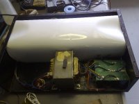
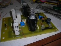
Quasi, here is a picture 😉
quasi said:
Congratulations Malik123, Any pictures ?
Cheers
Q
Quasi, here is a picture 😉
An externally hosted image should be here but it was not working when we last tested it.
Will a normal household thermometer not give a rough idea if it is working okay or not?
If I have to use two angles back to back like Quasi has said, I still have to unbolt all the output transistors. I was looking to avoid doing that. If I am going to remove the angle that is already in place to add one more, I might as well buy a 5 or 6mm angle and use it.
I could try out one thing though. I will do a trial run with the present setup. If the IRFs are getting too hot, I will dismantle the thing and use a 6mm angle. What do you guys think?
One more doubt: Will the 200R and 1K trimmers show different values when measured in-circuit?
Malik, congratulations! Neat work, mate.
Re: Re: Re: Nmos200
Nice work Malik123. The second stage transistors should have a small heatsink though.
Cheers & enjoy your amp.
Q
malik123 said:
Nice work Malik123. The second stage transistors should have a small heatsink though.
Cheers & enjoy your amp.
Q
Vivek said:I could try out one thing though. I will do a trial run with the present setup. If the IRFs are getting too hot, I will dismantle the thing and use a 6mm angle. What do you guys think?
One more doubt: Will the 200R and 1K trimmers show different values when measured in-circuit?
Hi Vivek, yes you could try to see how hot the FETs get, but the problem you have is once it's in a case with the lid on you may never know how hot they get. Still you might get some idea.
The trimmers will show different values in circuit. The 1K is connected to two 220R resistors and this becomes a parallel-series network. The 200R is connected to the base of T8 and depending of the polarity of your meter leads you will see the base emitter or the base collector junctions of T8.
Cheers
Q
I could always keep the amp without a case (or atleast without the top) till I am sure that the output transistors are not overheating. Or maybe I could use a fan.
Quasi, I have one question. I have build your amp, version with 5+5 fets per channel, but having some troubles. It works perfectly with 4+4 fets, when I solder 2 more of them it goes crazy, but only with load. Without is working normally. The same is if the load is higher (if add some resistor serial to load). I used 8 ohms load, PSU +-30 and +-75 with no difference. The fets are SPW20N60S
Emitter resistors are 0,33 ohm.
What could be wrong ?
Regards
Emitter resistors are 0,33 ohm.
What could be wrong ?
Regards
Hi Sulc,
We need to know what "goes crazy" is. Is it oscillating, motor-boating, latching etc? In order to observe this you really need access to a scope.
Unfortunately the problem could be caused by any number of reasons, from a open track around the FET gate to poor quality components (especially capacitors).
Have you built one or two modules. If you have built two, you can compare one to the other.
Post some more information.
Cheers
Quasi

I have built 2 modules, they have same problem. I can post screenshot of distorted sine wave, but if i remembered correctly, there is a problem with zero crossing. Which capacitors could be problem ?
Regards
Regards
nmos200 abused but survived....
decided to give 2 of my nmos200
to a dj friend who is very abusive towards Amps
He Drives them Hard and clips them to death
without abit of compation.
most Amps never make it for more than 6 months
He used my stereo Nmos200 for driving 4X 8ohm 100w 12inch speakers for 7Hours Straight
And Guess What?
Even with the little Heatsinks I had on it (fan Cooled)
built with non exotic parts (ceramic caps)
50V rails (well 48.6 to be exact)
The Nmos200 made it back alive
Thanks quasi for sharing this briliant amp with us
and a couple of pics...

OK, i've made some more research.
Tested on +-75v:
No load, little clipped
With load, small input, on output:
With load, almost full input, on positive gate:
Negative gate, small input, with load:
When i look carefully, i saw there is an anomaly in curve even without load:
And i changed range:
Let i tell if i unsolder 2 emitter resistors, one per rail, problems are gone. So, here must be connection with number of fets per rail.
Regards
Tested on +-75v:
No load, little clipped
An externally hosted image should be here but it was not working when we last tested it.
With load, small input, on output:
An externally hosted image should be here but it was not working when we last tested it.
With load, almost full input, on positive gate:
An externally hosted image should be here but it was not working when we last tested it.
Negative gate, small input, with load:
An externally hosted image should be here but it was not working when we last tested it.
When i look carefully, i saw there is an anomaly in curve even without load:
An externally hosted image should be here but it was not working when we last tested it.
And i changed range:
An externally hosted image should be here but it was not working when we last tested it.
Let i tell if i unsolder 2 emitter resistors, one per rail, problems are gone. So, here must be connection with number of fets per rail.
Regards
Quite odd...
Hi sulc,
You have quite a strange issue here, even the crossover distortion is odd in the way it looks.
I assume you have set the amp up correctly and the no signal voltage measurements are correct.
With the 10 FETs on board first check that you are getting at least 30mA per FET pair or 150mA for the 5 pairs.
You could try these ideas in no particular order.
- Increase C8 to 33pF
- Reduce R20 and R22 to 150 ohm. This reduces the drive impedance for the output stage. Note this will make T9 & T10 very hot, so don't run in this mode for too long.
- Increase the gate resistors to 56 ohm.
- Increase c4 to 47pF
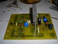
- Show us a piccie of the built PCB particularly showing C10, C9, C6, C5 and C12.
Cheers 😕
Hi sulc,
You have quite a strange issue here, even the crossover distortion is odd in the way it looks.
I assume you have set the amp up correctly and the no signal voltage measurements are correct.
With the 10 FETs on board first check that you are getting at least 30mA per FET pair or 150mA for the 5 pairs.
You could try these ideas in no particular order.
- Increase C8 to 33pF
- Reduce R20 and R22 to 150 ohm. This reduces the drive impedance for the output stage. Note this will make T9 & T10 very hot, so don't run in this mode for too long.
- Increase the gate resistors to 56 ohm.
- Increase c4 to 47pF
- Show us a piccie of the built PCB particularly showing C10, C9, C6, C5 and C12.
Cheers 😕

- Home
- Amplifiers
- Solid State
- Power amp under development