AndrewT said:Hi Quasi,
funny co-incidence.
I just happen to have 3pair apt30 in my Bensen spreadsheet.
It shows 300W into 4ohm @ 60degree phase angle, Tc<=53degC and it stays inside the DC SOAR.
The apt30 were added when Workhorse? was advocating their use some months ago.
Do you want the numbers for 100mS? since this fits your reliability criteria more closely.
Yes please.
Cheers
Hi Quasi,
you will have Email in a few minutes, but if you can't wait, salivate over this:
600W into 4ohm @ 60degree phase angle, but only just inside the 100mS SOAR @ Tc<=45degC.
you will have Email in a few minutes, but if you can't wait, salivate over this:
600W into 4ohm @ 60degree phase angle, but only just inside the 100mS SOAR @ Tc<=45degC.
Hello John,
late reply, but... 😉
I too am having readily adopted schematics and board layouts for both the AV400 and the ZETA in my Eagle-projectbox. I chose not to build the former because of the same stability issues and the latter because of struggling project development by Lars. Anthony "The Saint" Holton, btw., still claims any stability issues of the AV400 to be a legend rooted in a combination of widespread, outdated schematics and wrong component placement print on his first revision boards (people illegally gave away his schematic and his board layout, others didn't understand the circuit and the documentation and just built).
The diff-stage transistors can be replaced by readily available MPSA42/92 for prototyping/testing purposes, as Lars also suggested. But sound will not be the same, really. The rest of the project seemed to go well, but it left the impression with me that Lars used to feel kind of forced into a project effort that he initially didn't really want to drive to this extent. Sadly he got too much to do and to cope with in order to keep the ZETA afloat and evolving (there have even been attempts to transform it into a rail-to-rail circuit with superb efficiency).
I hope everything is going better now, all the best from me.
As always, thanks John.
Sebastian.
late reply, but... 😉
keypunch said:Aside from the Holton N-Channel amp that caused me stability concerns form reading others experiences, I had looked at the initial Zeta design by Lars.
I too am having readily adopted schematics and board layouts for both the AV400 and the ZETA in my Eagle-projectbox. I chose not to build the former because of the same stability issues and the latter because of struggling project development by Lars. Anthony "The Saint" Holton, btw., still claims any stability issues of the AV400 to be a legend rooted in a combination of widespread, outdated schematics and wrong component placement print on his first revision boards (people illegally gave away his schematic and his board layout, others didn't understand the circuit and the documentation and just built).
I did not persue the Zeta design for a few reasons - local part availability of a couple of the transistor types, [...]
The diff-stage transistors can be replaced by readily available MPSA42/92 for prototyping/testing purposes, as Lars also suggested. But sound will not be the same, really. The rest of the project seemed to go well, but it left the impression with me that Lars used to feel kind of forced into a project effort that he initially didn't really want to drive to this extent. Sadly he got too much to do and to cope with in order to keep the ZETA afloat and evolving (there have even been attempts to transform it into a rail-to-rail circuit with superb efficiency).
I had an extensive set of life demands on me
I hope everything is going better now, all the best from me.
Hope my comments are helpful Sek.
As always, thanks John.
Sebastian.
65 W / 8, 100 W / 4 isn't problem with only one pair of 540/9540. Attested on hundrds of amps... Only by calculation of rail voltage you must remember, that voltage at VAS must be cca 7 V higher than voltage at power stage ( for good driving )...
AndrewT said:Hi Key,
I would never write ?W (with or without peak) when I mean ?Wpk.
In fact that even that would, in my view, be confusing and I would tend towards using ?Vpk to avoid the ambiguity. Similarly I write Ipk when I mean that.
Andrew,
Fair enough. I mentioned only to clarify rather than assume. For ~25VDC rails I would not expect much mroe than about 15W-20W RMS with respect to 8 ohm load. I would say one IRF540 pair would do fine in that case. For 65W RMS with 40VDC rails I say more likely to need 2 pairs of IRF540s for 8 ohm rated speakers. If one needed to use 4 ohm speakers I would suggest 3 pairs of IRF540s would be required.
marus said:
I just use the Quasi Power Matrix when i said 65W....
I think it's about TRUE RMS POWER those watts
This is what i will do : 😀
I will make a test PCB just with the low power section ... without power transistors and i'll try all transitors ( mosfet's and bipolars) to find one who works better. (single pair!)

Ok, makes excellent sense both in math and knowing the point of reference. From the IRF540 data I have and the calculations I have done you will likley need two pairs of IRF540 for 65WRMS based on my calculations which tend to be on save side. Quasi has a rule of thumb to do the calculations earlier in thread. You may wish to look at Post #116. for how quasi makes a rough calculation on the power handling . In Post #1393 I listed my calculated power handling for a Pd of 70C and 60C for the IRFP450, IRF840 and IRF540. This is the maximum power rating is no matter what the speaker impedance is. For the IRFP450 you will be able to compare the different ways and values arrived at for the IRFP450 others have used to determine what they regard as the net power rating which can be based on the intended application of the amplifier, i.e. home HiFi, PA, speaker load, speaker crossover newtwork used, ambient air temperature, heaksinking used, ect.
If you take the calculated device power rating for the operating conditions your design requires as the 8 ohm impedance then to be able to handle a 4 ohm load you need to have two pairs, for 2 ohm load 8 pairs while maintaining the rated 8 ohm power rating desired.
My calculations are based on the device power derating for the operating device temperature and a deduced current rating from the device datasheets. Though I do not expect the devices to operate at such high temperatures I choose such temperatures in part as a factor of my safety margin in a design.
There are more in depth discussions related to SOA calculations through the thread if you wish to seek a deeper understanding of. I will skip posting links for as you should be able to find those pockets of discussions reading the thread and some of them when searching the thread.
Regards,
John L. Males
Willowdale, Ontario
Canada
19 January 2007 05:04
1/4w resistors possible for nmos200?
Hi,
Really great thread!
Thank you so much quasi and many people here.
I'm enjoying this thread nowadays.
Happily, so many posts to enjoy~
I have a quick question.
Can I use 1/4w metal film resisters for nmos200
except R27-R35?
I have many of them but don't have 1/2w ones.
Hi,
Really great thread!
Thank you so much quasi and many people here.
I'm enjoying this thread nowadays.
Happily, so many posts to enjoy~
I have a quick question.
Can I use 1/4w metal film resisters for nmos200
except R27-R35?
I have many of them but don't have 1/2w ones.
Re: 1/4w resistors possible for nmos200?
Welcome to the thread Cantabile. Yest 1/4 metal film will be fine.
Cheers
Quasi
cantabile said:Hi,
Really great thread!
Thank you so much quasi and many people here.
I'm enjoying this thread nowadays.
Happily, so many posts to enjoy~
I have a quick question.
Can I use 1/4w metal film resisters for nmos200
except R27-R35?
I have many of them but don't have 1/2w ones.
Welcome to the thread Cantabile. Yest 1/4 metal film will be fine.
Cheers
Quasi
Keypunch, Andrew and Quasi, sorry that I had not looked at your respective posts earlier.
The distortion issue is something that I need to tackle and am confident of pinning down when I open up the case of the amp again. When I do, I will report my findings for the benefit of all.
Regarding the sound quality, I think that the higher Forward Transconductance of the IRFP460 plays a positive role.
I have achieved pretty good sound with single pairs of IRFP260s in Bengt Olson's N-channel amps, from which Anthony Holton's N-channel was derived. While using IRFP260s I have consistently experienced a darker background to the music and more solid low end. These are certainly attributable to high input capacitance. Although the drive stage struggles in both the above mentioned designs, the very high yfs=23S of the 260s contributes greatly to sound quality.
My bet for Quasi's N-channel with single OP pairs would be IRFP264, IRFP460 and IRFP260 in that order. I have not yet been able to source 264s but I am pretty sure that most would prefer the sound quality that this should produce.
Quite some time ago, I tried posting some mods that I wished to propose for Quasi's amp, but I made the drawings in .bmp and simply could not post these. If someone can catch the point, my proposal is to replace the two string diodes with a transistor to make the current source/sink, split the 27k resistor to ground and decouple the junction point of the two resistors with a cap and replace the MJE340 with IRF610. This is on the side of the negative rail.
On the positive rail side, it would be nice to make a cascoded VAS with a small bjt like 2N5401 and IRF9610 and the miller cap could go from the Base of the bjt to the drain of the Mosfet. Appropriating dimensioning of the Resistors around these modified stages is a must and instability issues if any, should be addressed.
Further, either the front end should have its own regulated supply which is about 5 volts higher or decouple the power rails of the stage preceding the driver stage with a series connected diode/resistor with its own decoupling.
If the above proposal is to be implemented successful, one can put the revised Quasi on the same league as very high end amps.
Any thoughts on these thoughts?
Samuel Jayaraj said:Keypunch, Andrew and Quasi, sorry that I had not looked at your respective posts earlier.
Regarding the sound quality, I think that the higher Forward Transconductance of the IRFP460 plays a positive role.
Do you have any ieda why this is either in terms of prior experiences, testing or theories by yourself or others?
I have achieved pretty good sound with single pairs of IRFP260s in Bengt Olson's N-channel amps, from which Anthony Holton's N-channel was derived. While using IRFP260s I have consistently experienced a darker background to the music and more solid low end. These are certainly attributable to high input capacitance. Although the drive stage struggles in both the above mentioned designs, the very high yfs=23S of the 260s contributes greatly to sound quality.
My bet for Quasi's N-channel with single OP pairs would be IRFP264, IRFP460 and IRFP260 in that order. I have not yet been able to source 264s but I am pretty sure that most would prefer the sound quality that this should produce.
What is yfs? Is it really Gfs = Forward Transconductance?
Darker background means less background hiss noise at idle and when play material? If this is so could this not be measured or characterized via a scope view at idle?
Without having to yet source IRFP264's why do you feel the IRFP264 would be better than the IRFP460 or IRFP260?
I know you stated the IRFP460 was better than the IRFP450. Is it possible that there may be a PSU element in terms of noise, ripple, artifacts that perhaps "slower" devices mask out? Perhaps the higher Ciss is indirectly filtering out some artifacts of the PSU? On flip side is it possible faster devices are more sensitive to RF that maybe entering into feedback and making the amp sound less dark? If this was case, it is possible the musicality may be being impacted by the backgound noise summed with the output single and/or feed back to the input diff pair via the NFB path and/or the low end lacks the strength due to the PSU rails being drained with less dark signal. The higher Ciss at progressively lower D-S voltages may be providing a sliding scale of PSU filtering to result in the darker background. It would be interesting if you first tried the Leach Feedforward NFB in the quasi design and retested the IRFP450, IRFP260, IRFP460 and see if there is any difference.
Did you still use source resistors with your single pair versions? If so what resistance did you use?
With respect to the higher Ciss. I think it was suggested a lower Ciss is desirable for the output devices. Then later it was indicated the Ciss in the design did not have much as much impact as commonly accepted either with this design or in general. Given the design is for 3 pairs of IRFP450's whose Ciss sum would be greater than any of the one devices you used I would be of the opinion that the Ciss being higher for the devices you used for the single pair to be less and therefore not a factor. However once you have the distortion matter resolved for your 3 pair midules that use the IRFP450s and you find it on par, better or worse than the single pair versions you tested that to me would suggest the design either favours higher capacitance or there is additional PSU artifacts being filtered by the higher and sliding Ciss sum of the output devices.
Quite some time ago, I tried posting some mods that I wished to propose for Quasi's amp, but I made the drawings in .bmp and simply could not post these. If someone can catch the point, my proposal is to replace the two string diodes with a transistor to make the current source/sink, split the 27k resistor to ground and decouple the junction point of the two resistors with a cap and replace the MJE340 with IRF610. This is on the side of the negative rail.
On the positive rail side, it would be nice to make a cascoded VAS with a small bjt like 2N5401 and IRF9610 and the miller cap could go from the Base of the bjt to the drain of the Mosfet. Appropriating dimensioning of the Resistors around these modified stages is a must and instability issues if any, should be addressed.
This is well beyond anything I would understand. That said, I personally like the BiPolar prediver as I think it balances the pros of BiPolar and the Pros of the MOSFET N-Channel output stage.
Further, either the front end should have its own regulated supply which is about 5 volts higher or decouple the power rails of the stage preceding the driver stage with a series connected diode/resistor with its own decoupling.
I am not sure a higher voltage for the front end will have any improvement. Quasi's initial design was one with a regulated PSU for the front end and higher voltage for the front end. Quasi spent some time at this and even took the time to add some secondary windings to his toroid to effect this. You find all of the related discussion and tests in the first part of the thread until the design changed to the single PSU.
One of the PCB changes I have have yet to effect is to seperate the front end from the output stage, add some PCB PSU rail filtering and add a seperate PSU for the front end. Will I use a regulated PSU for the front end? I do not know, but at least it will be seperate and with own PSU filter capacitors and reserve. I would hope even though the front end in this case will still be the same rail voltage as the output stage it will at least isolate some of the current ebbs of the output load, reduce the back EMF, capacitance and reactance from speakers the front end will see, and hopefully isolate the front end to some of the voltage/current fluxes caused by the output load. Ideally if I could find seperate transformers of the same voltage as the output stage transformer then I would use a seperate transformer as at lest for sure there would be no voltage drop seen at all by the front end due to the load at the output. Even if the transformers were a few volts higher as long as their price and size was acceptable I still take that additional step, but not so I could have the front end at higher voltage. If such transformers were above a few volts higher I likely not consider based on quasi's findings in this regard. I suspect just adding a seperate bridge, filter bank capacitors from the same transformer for the front end will make some improvements with little extra cost. I cannot confirm this as I am not that far along to try. I cannot see it will be of any harm or negative impact to the single supply approach.
If the above proposal is to be implemented successful, one can put the revised Quasi on the same league as very high end amps.
Any thoughts on these thoughts?
Regards,
John L. Males
Willowdale, Ontario
Canada
20 January 2007 03:19
20 January 2007 03:40 Typo correction
Besides the power stage changes i see that are diferences in the input stage from nmos350 to nmos200 schematics :
R3, R17 from 33K to 27K
T1 T5 from 2SC1845 to BC546
R6 from 18K to 10K
Why ? The imput stage isn't the same for all output power versions ?
😕
R3, R17 from 33K to 27K
T1 T5 from 2SC1845 to BC546
R6 from 18K to 10K
Why ? The imput stage isn't the same for all output power versions ?
😕
Keypunch, I agree with many of the concerns you raise but I should state that Audio is not all pure science, numbers and theory but equally intuitive and subjective; intuitively, one balances all parameters to make choices of components, topology, layout etc., and the more you figure out the devil in the details the more intuitive you become.
Yfs, I guess is also used in place of Gfs, or so my memory tells. Anyway, I did mean Forward Transconductance. The higher the figure you have here, the lower the distortion numbers are likely to be, all else being constant. That is why you will find a preference for IRF/IRFP 044 parts in the Pass Forum, if the power ratings would allow this for a given application.
You do make an interesting point about Ciss filtering out PSU artifacts and RFI/EMI. This could be quite a possibility. But I guess there are other factors as well. I think, it was YBA who first used a Blue LED to 'soothe' the 'jittery' laser in their CD players; this resulted in a more musical signal and a 'darker background to the music'. An attempt to describe the phenomenon would go something like this - if music being played/heard through your chain can be compared to a painting, obviously the painting should be on some canvas..... The way you perceive the vividness of the colours would to some extent depend on whether the canvas is white, black or anything in between. The contrast would be the highest if the canvas were the blackest possible, and the black background can sometimes be as gripping as the painting itself. Now suppose, the painting also vividly portrays a third dimension of depth, with layer after layer of depth, then the background will get pushed behind the last layer and because of all of the Gestalt principles, depth is perceived as 'deeper' than it would be if the background were lighter or tending towards white. What happens in this scenario is that the foreground is the most prominent with successive layers becoming more obscure and the background being both obscure and prominent at the same time depending upon one's perception.
I could go on to the best of my ability without being sure if I am being understood the way I intend to be. Try and figure it out. Someone else could pitch in with their perspective.
If one were to try Mosfets with very low capacitance that the driver stage sees, in some circuits, the highs can get a bit splashy (again like bleeding of colours in video). Try one with a little higher capacitance and this phenomenon can be controlled. Beyond a point, you tend to loose the shimer in the highs while you get the benefit of a more rigid bass. You have to choose the right balance somewhere. That is why I would still bet on the IRFP264 even before I am able to source it. Remember that my choices are limited to what is available and not by what is desirable.
marus said:Besides the power stage changes i see that are diferences in the input stage from nmos350 to nmos200 schematics :
R3, R17 from 33K to 27K
T1 T5 from 2SC1845 to BC546
R6 from 18K to 10K
Why ? The imput stage isn't the same for all output power versions ?
😕
R17 was changed so that the gain makes more sense for rails of 50 volts. R3 was changed to match. T1 & T5 was changed to BC546 because it is more common and is suitable for lower rails. The only reason the 2SC1845 found a place in the amp was because of it's high Vce, but at $1.00 each I'll use them where they are needed. R6 was changed to 10K so that it did not drop as much voltage leaving enough across T4 so that it worked properly.
Anyway here's a pic of a half completed Nmos200, waiting for it's output stage.
Cheers
Quasi
Attachments
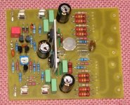
Very very very nice "half completed Nmos200" 😱
I'm looking forward to make this version.
So .... this nmos200 meens 200W RMS on 8 hmms ?
I'm looking forward to make this version.
So .... this nmos200 meens 200W RMS on 8 hmms ?
marus said:Very very very nice "half completed Nmos200" 😱
I'm looking forward to make this version.
So .... this nmos200 meens 200W RMS on 8 hmms ?
Marus,
The 200W rating is for 4 ohms, therefore the 8 ohm rating would be 100W assuming output devices of suitable power handing ability are used. This assumes a well designed power supply.
Regards,
John L. Males
Willowdale, Ontario
Canada
20 January 2007 18:57
Samuel Jayaraj said:Keypunch, I agree with many of the concerns you raise but I should state that Audio is not all pure science, numbers and theory but equally intuitive and subjective; intuitively, one balances all parameters to make choices of components, topology, layout etc., and the more you figure out the devil in the details the more intuitive you become.
Understood. At my level of knowledge and my "tinkering" of the numbers I persist along that line due my skill not like many on the forum and partly as part of my process to either learn the intuitive side from my more science side questioning. Part of why I ask so many questions is because I am trying to do the best I can the first time. I do not have the time nor the money to be building 21+ amps a few times over until I am close to what I wanted. I also hope with my untrained skills and natural curiousity and questions I might actually open the odd new insight that might lead to some element being better understood, proven with testing and ears to move a bit more forward.
My intutive and reading/reasearch has brought me to the N-Channel design. I have already indicated how I arrived at setting on the quasi design for most part in this thread. My instincts tell me that the quasi amp is one of the best amps due to the simple design that provides excellent sound quality with many well known easy to find and understood parts. My noted changes in my opinion are minor and do not add much complexity to the existing quasi design. I am still not sure I will implement the Leach Feedforward NFB, but I know I will make the PCB flexible to add in if I decide to later after some comparisons both on bench and listening. The seperation of the front end PSU is a simple change in my opinion and at least will have some benefit, maybe alot of benefit. Again an easy change and easy to add in and do comparitive bench and listening tests. Listening tests have to be done over a few months in my opinion.
The PSU for the front end is already a well established improvment for amy amp I have read about to date. The Leach Feedforward NFB is interesting and so I like to see if has any upside as it is not all that complicated and only adds a couple more parts to the amp part count. Things like balanced inputs, metering, and such are just add ons that do not afect the base amplifier. DC protection I think is a must though purists may disagree.
Yfs, I guess is also used in place of Gfs, or so my memory tells. Anyway, I did mean Forward Transconductance. The higher the figure you have here, the lower the distortion numbers are likely to be, all else being constant. That is why you will find a preference for IRF/IRFP 044 parts in the Pass Forum, if the power ratings would allow this for a given application.
The yfs or Gfs comments and observations you made has added one more "science" bit that I will churn over the numbers and see if I can find a relationship to help predict.
I had been thinking of the Pass amps, but decided not to draw a comparison as they are pure Class A. Class A has different demands and state that may need a different set of key parameters for the "ideal" output device. Clearly the PSU esign for Class A has some unique needs specific to Class A that are not suitable for Class A/B amps.
You do make an interesting point about Ciss filtering out PSU artifacts and RFI/EMI. This could be quite a possibility. But I guess there are other factors as well.
Thanks. Again just an idea I had with the limited and different way I look at things with my limited design knowledge. It was just a thought which may have no basis of fact. I tossed out the thought just in case those in know migght offer some suggestions on the valility or non-valility of the observation I made.
I think, it was YBA who first used a Blue LED to 'soothe' the 'jittery' laser in their CD players; this resulted in a more musical signal and a 'darker background to the music'. An attempt to describe the phenomenon would go something like this - if music being played/heard through your chain can be compared to a painting, obviously the painting should be on some canvas..... The way you perceive the vividness of the colours would to some extent depend on whether the canvas is white, black or anything in between. The contrast would be the highest if the canvas were the blackest possible, and the black background can sometimes be as gripping as the painting itself. Now suppose, the painting also vividly portrays a third dimension of depth, with layer after layer of depth, then the background will get pushed behind the last layer and because of all of the Gestalt principles, depth is perceived as 'deeper' than it would be if the background were lighter or tending towards white. What happens in this scenario is that the foreground is the most prominent with successive layers becoming more obscure and the background being both obscure and prominent at the same time depending upon one's perception.
I could go on to the best of my ability without being sure if I am being understood the way I intend to be. Try and figure it out. Someone else could pitch in with their perspective.
Samuel, nobody needs to jump in. You made you point quite well and I follow.
If one were to try Mosfets with very low capacitance that the driver stage sees, in some circuits, the highs can get a bit splashy (again like bleeding of colours in video). Try one with a little higher capacitance and this phenomenon can be controlled. Beyond a point, you tend to loose the shimer in the highs while you get the benefit of a more rigid bass. You have to choose the right balance somewhere. That is why I would still bet on the IRFP264 even before I am able to source it. Remember that my choices are limited to what is available and not by what is desirable.
Your comments about Ciss are interesting. I have invested in APT4025BN's quite a bit after much research and review of opinions across many different designs. I chose the APT4025BN for the flat capacitance curves, high power handling, and their on/off and rise\/fall times while taking into consideration device selection and impact on cross conduction.
I agree and understand the balance that needs to be struck. I am also very aware of your choices being limited by what is available in you neck of woods. Even so, you have made some very interesting observations compared to the IRFP450 that bears some further understanding.
Regards,
John L. Males
Willowdale, Ontario
Canada
20 January 2007 19:45
20 January 2007 19:47 Typo correction
Re: Nmos200 TO247 version.
.... and this could be the schematics ?
quasi said:.
A pair of 250 or even 300 watt TO247 could be interesting.
nmos200-to247 layout & tracks.pdf
Cheers
Q
.... and this could be the schematics ?
Attachments
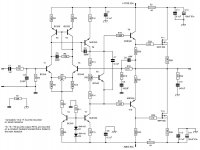
Re: Re: Nmos200 TO247 version.
Yes, that wouild be the schematic.
R29, R30 should be 5 watts.
Regarding R34. At 20Khz and with 50 volt rails it will dissipate under 1 watt, so aa 2 watt resistor is fine. If you test the amp at 20 Khz for an extended period this resistor will get hot though.
All others can be 0.25 watts although 0.5 watt metal films are about the same size and price.
Cheers
Q
marus said:.... and this could be the schematics ?
Yes, that wouild be the schematic.
marus said:0,27 ohm R29,30 = ?? watts
10 ohm R34 = ?? watts
I think the rest could be 0,25W .... 😕
R29, R30 should be 5 watts.
Regarding R34. At 20Khz and with 50 volt rails it will dissipate under 1 watt, so aa 2 watt resistor is fine. If you test the amp at 20 Khz for an extended period this resistor will get hot though.
All others can be 0.25 watts although 0.5 watt metal films are about the same size and price.
Cheers
Q
Hi Quasi,
do the emitter resistors really need to be 5W?
If 6Aac were passing through them continuously then 5W would run very hot.
However, 150W into 8r needs an output current of 6.1Apk and rms equivalent of about 4.3A.
This current flows to output from one or other of the emitter resistors when operating at full power in the ClassB mode so the heating effect is the equivalent of just half power lost through the resistor.
Pd 0.5*4.3^2*0.27=2.5W (=Isquared R loss).
That's for a single pair of output devices and becomes even less onerous when multiple pairs are adopted.
Then take account of peak to average music power and the emitter resistors are going to run cold to warm in normal music reproduction. Only full power testing is going to put 2.5W (each) or so through any single pair of emitter resistors and that takes a mighty big single FET to do that during testing.
- Home
- Amplifiers
- Solid State
- Power amp under development