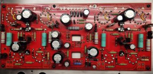
Hopefully one day I can pay back 10-fold for my questions and need for hand holding. I populated the Red Board and think I got the changes made that were recommended. When I ordered the parts I didn't quite know what route I was going to take.. increasing power to the board or with the 'boost method' so I went with upgrading the capacitors. Reading through this thread a few times it really dawned on me that this is old history already.
C2, 3, 6, 21, 24, 25, 27 increased to 47uf 500v
C4, 5, 22, 23, 26, 30 increased to 10uf 500v
D1, 2, 3, 4 increased to 3A 1000v
R8, 9, 10, 11 changed to 500 ohm (had to put 2x 250 ohm 1w in series)
Mod was done according to image at post 346 to run 6HJ5 tubes
Additional Jumper added to 12 pin sockets between pin 2 & 4 to accommodate 6HD5 tubes according to a certain super smart 'axe' wielding blond guy in post 1869
R29, 30, 31, 47 changed to 220k 5 watt
Reduced R21 to 1k 5 watt
I haven't done anything with the 820pf caps yet and the FETs are waiting until the heatsink arrives so I can twist my addled aging brain a bit more 🙂
Attachments

Yeah, 15 years went by way too fast. 😱Reading through this thread a few times it really dawned on me that this is old history already.
jeff
Hi all,
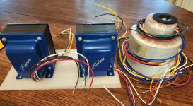
The transformers have finally arrived! Man, folks were not exaggerating the weight of this thing as a 100 watt per channel amp!
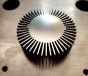
I stole the round heatsink idea from many of you here. Tubes are all here 🙂 . Now I'm waiting on another chassis. I'll keep the original for a stock build or just slightly larger but I don't think it would support all the weight very well. I think I might have bitten off a bit more than I can chew here. I decided to go with the build that Scott17 put together using 2 Antek AS-2T230's, a little 25va 40+40 for bias etc. Scott's not available but I'm hoping I can bug some of you when it comes time to wire this up 🙂
The transformers have finally arrived! Man, folks were not exaggerating the weight of this thing as a 100 watt per channel amp!
I stole the round heatsink idea from many of you here. Tubes are all here 🙂 . Now I'm waiting on another chassis. I'll keep the original for a stock build or just slightly larger but I don't think it would support all the weight very well. I think I might have bitten off a bit more than I can chew here. I decided to go with the build that Scott17 put together using 2 Antek AS-2T230's, a little 25va 40+40 for bias etc. Scott's not available but I'm hoping I can bug some of you when it comes time to wire this up 🙂
Attachments
Hello to everybody!
I know that @Tubelab_com have used this amp as a guitar amp; I want to ask how does it performs as a guitar amp (obviously with a preamp), thanks for your answers.
I know that @Tubelab_com have used this amp as a guitar amp; I want to ask how does it performs as a guitar amp (obviously with a preamp), thanks for your answers.
15 years? A long time?
My youngest Granddaughter is 16 years old.
I still have the tube amplifier chassis I purchased in 1995, 29 years ago.
It has been torn down, and rebuilt as completely different tube amplifier topologies, probably 20 times over.
SE, PP, DHT, Pentode, Beam Power, Stereo, Mono-block, LTP stage, Interstage, RC coupling, JFET CCS, Choke CCS, Auto transformer phase inverter; and tube-rolling.
A workhorse chassis, the only items that are always the same are the power transformer and the chassis.
Try designing different amplifiers around a single power transformer that only has one center tapped B+ secondary, and two 6.3V filament secondaries. Oh, I forgot the 5V secondary, Early-on, I stopped using tube rectifiers.
Last edited:
Not so long in life terms but ages as far as on-line attention span 🙂 I'm positive Mr. Millett's amplifier designs will outlive us all!15 years? A long time?
My youngest Granddaughter is 16 years old.
Bump.Hello to everybody!
I know that @Tubelab_com have used this amp as a guitar amp; I want to ask how does it performs as a guitar amp (obviously with a preamp), thanks for your answers.
Anyone?
It wasn't designed to be a guitar amp, but that doesn't stop you from hooking it up and pi$$ing off the neighbors. 😉
jeff
jeff
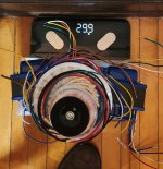
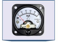
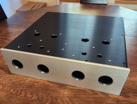
Let the games begin! The new chassis has arrived. Now we are officially over the 40 lb. mark with just chassis and transformers. Definitely in need of handles of some kind. I found a person in the 'Orient' to build the chassis and cnc cut the board and panel meter holes. The front panel is 8mm thick with top and bottom @ 3mm. To me it would have proved very daunting getting those holes made so perfectly. Ordered on the 23 October and arrived about an hour ago. 42cm x 41cm x 12cm (rough external measurements) should leave tons of room for everything. Would it be worthwhile doing a sort of 'inept newbie' build thread? I know I had tons of questions getting just this far with many more guaranteed to come up.
Attachments
- Home
- Amplifiers
- Tubes / Valves
- Posted new P-P power amp design