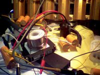
I set up the PFC module for some testing to see how the aux. cap (across the bridge rectifier output) would perform to reduce zero crossing ripple. The results were illuminating but somewhat disappointing. The setup used a 470 uF electrolytic cap on the 360 VDC output. Input AC thru a 250 VA isolation xfmr and 500 VA Variac with a Corcom F2214A line filter.
With a 43 Watt load (3K Ohm) on the PFC, the 360 V ripple was around 1.5 V p-p and with a 218 Watt load (600 Ohm) around 8 V p-p. Adding a 10 uF aux. cap reduced the 43 Watt ripple by about 10% but had no effect on the 218 Watt level. Checking the voltage on the aux. cap showed that it was maintaining 74 V minimum (at AC zero crossing) on the 43 Watt load and 22 V min. on the 218 Watt load.
The shape of the output ripple waveform is between a triangle and sine wave in either case. Apparently the problem is not from the momentary dropout at zero crossing, but rather the overall variation of the 60 Hz AC waveform modulating the PFC current supplied to the output 470 uF cap. Doubling up the 470 uF cap to twice that drops ripple in half. I also tried putting another bridge rectifier in front of the module with a 470 uF cap there and that dropped the ripple by 3X.
Putting a 55 uF aux cap in, instead of the 10 uF aux cap, did improve some of the results noticeably (the 43 Watt case sent the 60 Hz ripple down below the switching noise), but it also seems to produce some kind of low freq instability in the PFC control under some load and input voltage conditions, so appears to be not real useful. (also looks like for heavy loads, the aux cap will have to be just as big as the output cap., so just a brute force effect anyway)
Although it could be that the additional line resistance from the isolation xfmr and Variac in the input string are part of the LF instability cause, allowing the line voltage to fluctuate downward when the PFC tries to draw heavy current. Possibly an RC constant occurs between the series xfmr resistances and the 470 uF output cap, and I suppose the PFC itself looks like some kind of inductor. I've noticed a similar effect before with big (750 VA) PF corrected power supplies if you put two of them on the end of a long extension cord without individual line filters with big AC caps for each.
So end result, for lower ripple, use a bigger electrolytic cap on the 360 VDC output.
Attachments
Last edited:
I tried the aux. cap test on the PFC module again (470 uF main cap on the output) WITHOUT the Variac in the input (to reduce the input line resistance, especially the carbon brush effect) and got much better results this time.
At 218 Watts load, I get 6 V p-p ripple with no aux. cap, 5.9 V p-p with a 10 uF aux. cap, 4 V p-p with the 55 uF aux cap, and 1 V p-p with a 470 uF aux. cap. If I put the extra 470 uF cap on the output instead (total 940 uF) with no aux. cap I get 3 V p-p ripple.
At 43 Watts load, I get 1.4 V p-p ripple with no aux cap, 1.3 V p-p with the 10 uF aux. cap, 0.4 V p-p with the 55 uF aux. cap, and about .2 V p-p (120 Hz ripple) with the 470 uF aux. cap. (buried in the switching noise of around 1 V p-p)
No sign of the LF instability at either load with 470 uF aux. cap this time. But the 55 uF aux cap did still cause LF instability.
Looks like the aux. cap position is 3X more effective at reducing (120 Hz) ripple than adding to the output main cap. for high power (218 Watt), and 3.5X more effective at the 43 Watt level.
But the input current waveform is about 1.5X more peaked with the 470 uF aux. cap. in circuit. The 55 uF aux cap made 1.5X more peak current draw at 218 Watt, and 1.5X more peak current draw at 43 Watt. The 10 uF aux. cap has hardly any affect on the input current waveform at high power, but some small peaking at low power. Adding the extra 470 uF cap to the output main cap (940 uF total) made no difference to the input current draw for low or high power.
Last edited:
"Aux, you mean unPFC'd right after the bridge? "
Yes, I'm using the aux cap, right after the bridge, to hold the apparent "input voltage" up above zero during the AC zero crossing. Allowing the PFC to still convert from that stored charge until the real input comes back up. Seems to have a 3 to 1 advantange over adding the same capacitance to the output cap. Except, of course, the power factor, or current spiking, on the input line gets worse. I guess one could put a current limiting resistor in series with the aux. cap, with a diode across it to allow fast energy withdrawal by the PFC, then the input current spiking could be reduced by spreading it out over the half cycle, but would probably reduce the cap effectiveness factor.
I suppose the ideal solution would be to use a 2nd PFC module after the 1st (no aux. caps), acting like the DC/DC converter normally used there. When it starts raining cheap PFCs anyway..............
Or an isolated 360 VDC PWM regulating converter, even better yet.
Last edited:
I think I have figured out the cause of the above mentioned LF instability of the PFC control using 55 uF for the aux. cap. The 250 VA isolation xfmr in front of the PFC has a leakage L of about 9 mH. The LC combo would be resonant at around 226 Hz, so was likely some beat freq. between the LC and the 120 Hz rectified AC.
Which brings me to an interesting possibility for getting rid of the 120 Hz ripple on the PFC DC output. The aux cap should be resonant right at 120 Hz with the xfmr leakage L. That way it draws a 120 Hz sinusoidal charge current, and self regulates to the average DC voltage level (the more it is discharged at the end of a cycle, the further it swings back up on the next cycle due to resonant excitation). The aux cap will still have some 120 Hz ripple on it, but sitting on the average rectified DC, and will be minimized by the resonant charging. Ie, it will have very low impedance from the power line due to the series resonant LC. (the xfmr leakage L will effectively be nulled out by the resonance, removing its blockage impedance. This baby will be able to suck the fuel out of the power line!)
The current draw on the power line will still be sorta sinusoidal too, although at 120 Hz chopped and re-fitted, guess that will look like 60 Hz plus 3rd harmonic. The input voltage for the PFC will then look like the typical ripply DC provided in any converter supply, and the 360 VDC output quality should be excellent.
Will experiment with this as soon as I get some free time.
The leakage L of the 10 Lb boat anchor xfmr, as seen from the secondary, is 2.8 mH. I guess they put more insulation between windings in isolation xfmrs to get the 9 mH.
Last edited:
Heh.., that isolation xfmr was a Triad-Magnetek N-90MD medical grade unit. At 9 mh leakage L and 119 pF common mode capacitance, obviously plenty of insulation in there. I just tested a more recent, made in China, Triad N-66A isolation xfmr, only 0.67 mH leakage and 310 pF common mode capacitance. Both 250 VA rated units. Not much insulation between windings apparently. ....patient electrocuted......
Last edited:
Hate to side track this alittle, but does anyone have a good way of converting heaters to dc without sucking an additional 40% power in the form of heat? I found this:
DC-DC Converter With Variable VDC Input
http://www.national.com/ds/LM/LM2576.pdf
It does 3amps min (charts are looking like 5amps or more with heatsink) and is 75% eff. Its a LDO with drop out voltage of 1.6v.
I figure the load is alittle over 10 amps with 6hj5's. Im just trying to reduce hum (sorry but it seems i have it unless the chassis is huge). The driver tubes only suck 1.2 amps, so i can easily convert those to dc the normal way.
Hmm on that note the 10 pounders were tested at 6 amps, not 10, wonder if i can just parallel the other 2 windings...
Hate to side track this alittle, but does anyone have a good way of converting heaters to dc without sucking an additional 40% power in the form of heat?
Why would you want to? With a little care in lead dress, you can run AC and still keep hum ridiculously low.
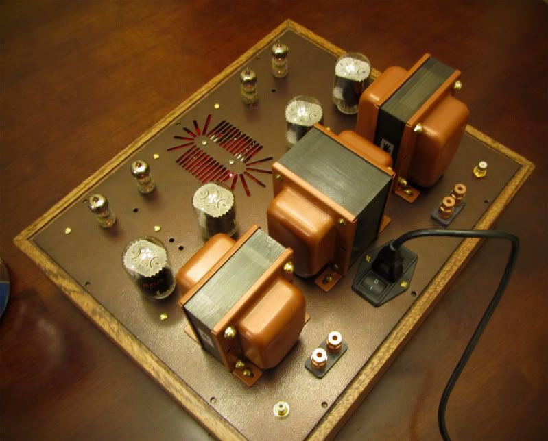
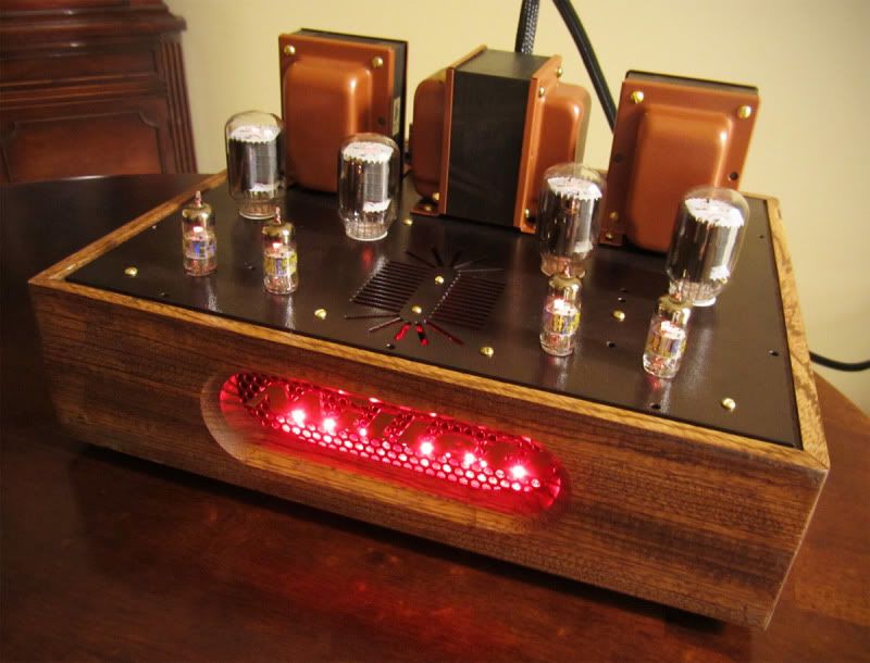
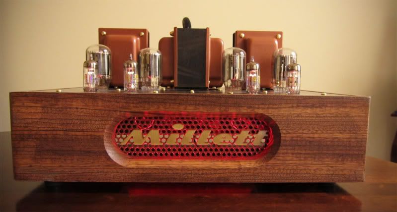
I didn't do any of the amazing power mods you guys are doing, but I finally finished my build.
You can find the rest of the build notes and photos here: DIY Audio Electronics from Zynsonix.com: The Millett DCPP Engineers Amplifier
An externally hosted image should be here but it was not working when we last tested it.
An externally hosted image should be here but it was not working when we last tested it.
An externally hosted image should be here but it was not working when we last tested it.
An externally hosted image should be here but it was not working when we last tested it.
You can find the rest of the build notes and photos here: DIY Audio Electronics from Zynsonix.com: The Millett DCPP Engineers Amplifier
Nice job, I like the wood and powdercoating. Backlight is a bit too much for my taste 😉
Can I ask why you chose the Ampohm capacitors over the Russian ones? What change did that make to the sound?
Can I ask why you chose the Ampohm capacitors over the Russian ones? What change did that make to the sound?
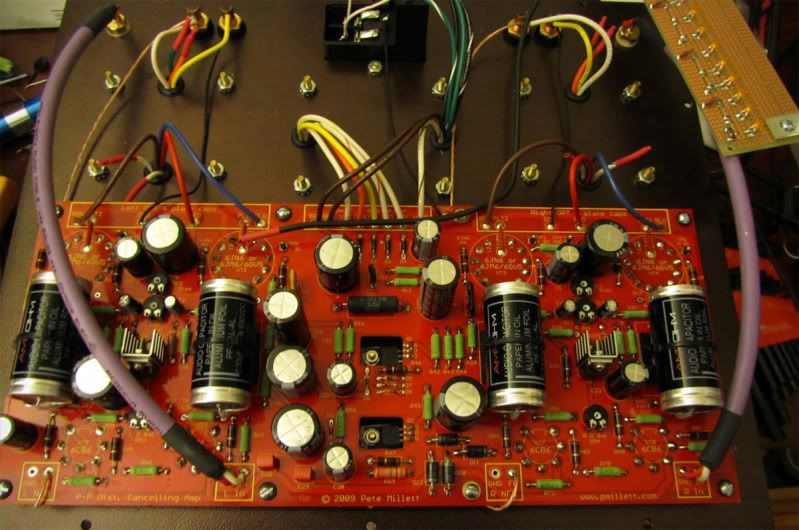
Wow thats a lot more electrolytics then i thought.
For the above 500 mods, lets see:
C8
C25
C2/C3
C24/C27
I think also C22/C30. Im also not sure why the 150v grid has all 450v caps since its regulated.
Ya i think im doing the stock 300v ish build with 3.3k load. I shouldnt need to change anything other then the full bridge rec right? Should I halve R21 to future proof it?
Ya i think im doing the stock 300v ish build with 3.3k load. I shouldnt need to change anything other then the full bridge rec right? Should I halve R21 to future proof it?
It seems that some tubes draw more screen current than others, and all tubes will draw more screen current when the plate voltage is lowered. When I was running my board on one 10 pounder I needed to lower R21. I just jumpered it with a clip lead for the single 10 pounder testing. I would lower it some, I am not sure if 2500 ohms is low enough, but it would be a good place to start.
Wow thats a lot more electrolytics then i thought.
For the above 500 mods, lets see:
C8 C25 C2/C3 C24/C27 I think also C22/C30. Im also not sure why the 150v grid has all 450v caps since its regulated.
Let me make something clear. When I was initially experimenting with the red board I attempted to raise the voltage that feeds the entire board. That led to a few mishaps and some exploded parts. I began installing higher voltage caps, until I found a better way. The way I and a few others are doing it now, NO high voltage caps are needed. All 3 of my boards are now built using Petes recommeded capacitors, except for places where I made substitutions to use parts on hand.
My current amp running at 600 volts has no capacitors rated higher than 450 volts anywhere. There is no voltage higher than 320 volts anywhere on the PC board escept for the output tube plates. I am using a second 10 pounder to provide 300 volts of "boosted B+" which is added to the main B+ and fed to the OPT's only. I have also used an isolation transformer to make 150 volts of "boost" to run the output tubes at 450 volts. I will document this better after more testing is done.
The only board mods are bridge rectifiers on B+ and bias supplies if the 10 pounders are used, and the value of R21. The stock 1 amp rectifiers are too wimpy for builds expecting over 100 WPC, use 3 amp diodes.
HIGHFLYiNG9's, Cool looking amp. I found this statment in your blog:
The design does has some MOSFETs in the driver, so tube-only purists may have to sit this one out.
This is not exactly true. THe mosfets and silicon diodes are in the power supply. The audio path is pure tube except for the CCS in the LTP tail. Some purists may still take issue with that. My currently experimental breadboard version does however stick mosfets in the driver, and a few other places.
I haven't had enough listening time with the newly modified amp to make concise statements on the AmpOhm caps, but will let you know when I do.
Thanks for the info 🙂 I went ahead and modified the verbiage so as to not mislead anyone.HIGHFLYiNG9's, Cool looking amp. I found this statment in your blog:
This is not exactly true. THe mosfets and silicon diodes are in the power supply. The audio path is pure tube except for the CCS in the LTP tail. Some purists may still take issue with that...
HiGHFLYiN9s out of curiosity what did it run you to have your end bells powder coated? The edcor blue doesn't go all that well with the color of my chassis.
Hi Nic, unfortunately with the Edcor Bells you're double dinged, you have to pay to get the blue powdercoat sandblasted off, then you have to pay for the new powdercoat. I had them painted with some other pieces all at once and my bill was over $100, but I'd imagine it would be ~$40-50 from your local powdercoater.
I think i smell what tubelab stepped in. R21 lightens the voltage drop load for the 150v regulator and (i assume)provides some current protection. So yes it can be small or jumpered if you decrease the input voltage such as using a b+ less then 350volts.
R21 lightens the voltage drop load for the 150v regulator and (i assume)provides some current protection
R21 absorbs some of the dissipation that would otherwise be burned up in the mosfet. At low B+ the resistor could be jumpered. It does have a "limiter" function and probably saved one or more of my output tubes when I did a dumb blonde move.
A pentode with a fixed screen voltage will draw less and less screen current as the plate voltage is increased. If the pentode is ever operated with screen voltage but no plate voltage the screen will attempt to draw all of the screen current AND all of the plate current. It will not live long if there is no current limiting. This should not be an issue the way we are using these boards. Even if you are using a boost transformer and forget to plug it in the voltage from the main B+ will flow right through the bridge rectifier and provide the plate with 300 volts.
I was however using the 10 pounder to run the board and a seperate bench supply to run the OPT's, and I shut my bench supply off. Within a few seconds R21 started smoking and I hit the bench kill switch. I was using a 1K 2 watt cheap Panasonic resistor for R21. It is quite toasty looking and all of the color bands are now black. It and all of the tubes survived, and still work. So it seems that 1K is a good "emergency" value since I think it would have died before the tubes did if I left the board powered for a few more seconds.
I have operated my amp that uses two 10 pounders with the second transformer unplugged. It works and makes about 35 WPC. This gives rise to the idea for a "turbo" switch to engage the "boost". The only issue is that I can't find a bias setting that works for both conditions. If the idle current is set for 35 mA with 600 volts I only get 25 mA or so with 300 volts. I think I need to wire a bridge on one of the heater windings of the second transformer to boost the bias when the second transformer is engaged.
Lol...boost. you read my mind.
Boost voltage (or correctly boosted B+) is a term from the days of vacuum tube TV sets. In a TV set the "boost" feeds the sweep tube. It is also made by the sweep tube and the damper tube! Very clever circuit to get two tubes to do three jobs. Our friend the horizontal sweep tube and the damper tube "sweep" the electron beam back and forth across the CRT, make the 25KV that runs the CRT and boost the B+ from 400 volts or so to somewhere in the 600 volt range. It runs at full throttle every minute the TV is on. Now you know why the later versions (from big TV's) are so tough. Ditto the damper tube (used as rectifiers in tube amps).
As with boosted engines you are just feeding the "engine" more of what it wants to eat. As with engines too much boost makes things blow up. Blowing up engines is a lot more expensive though. I have a lot of experience blowing up both.
Can someone recommend some flavors of 600v coupling caps? Looks like a cant use my favorite parts express foil bypass cap since its rated at only 400v. Or could i get 2 .47uf ones and run them in series, or would that sound like crap? Im trying to avoid spending more on caps then on tubes. Looks like one shipping bill is going to be just for caps.
http://www.tubesandmore.com/scripts...&SEARCH_TREE03=716PSERIES&SEARCH_TREE04=0600V
http://www.tubesandmore.com/scripts...RS&SEARCH_TREE02=11_SOLEN&SEARCH_TREE03=0630V
PS: post 750 said there needed 8 resistors for a 6hj5, are they still needed?
http://www.tubesandmore.com/scripts...&SEARCH_TREE03=716PSERIES&SEARCH_TREE04=0600V
http://www.tubesandmore.com/scripts...RS&SEARCH_TREE02=11_SOLEN&SEARCH_TREE03=0630V
PS: post 750 said there needed 8 resistors for a 6hj5, are they still needed?
Last edited:
- Home
- Amplifiers
- Tubes / Valves
- Posted new P-P power amp design