Can someone recommend some flavors of 600v coupling caps? Looks like a cant use my favorite parts express foil bypass cap since its rated at only 400v. Or could i get 2 .47uf ones and run them in series, or would that sound like crap? Im trying to avoid spending more on caps then on tubes. Looks like one shipping bill is going to be just for caps.
AES - Parts Catalog
http://www.tubesandmore.com/scripts...RS&SEARCH_TREE02=11_SOLEN&SEARCH_TREE03=0630V
PS: post 750 said there needed 8 resistors for a 6hj5, are they still needed?
I have used these Mallory caps and compared them to my Auricaps and I really couldn't tell the difference. If anything you could use these and switch them out at a later date if you so desire.
AES - Parts Catalog
I didn't really splurge but I picked up four Obbligato Copper Caps from Diyhifisupply http://www.diyhifisupply.com/node/72 for my red board.
Last edited:
PS: post 750 said there needed 8 resistors for a 6hj5, are they still needed?
I was referring to the screen and control grid stopper resistors. These are the same parts shown in the parts list (no additional parts), but they don't get put into the holes shown on the board. The pinout of the 6HJ5 is not the same as the tubes the board was designed for so the resistors get misplaced on purpose. Do not power up the board with 6HJ5's with the resistors in the stock location.
I have used these Mallory caps and compared them to my Auricaps and I really couldn't tell the difference.
I have heard statements that the Mallory's "sound harsh" and "are made for guitar amps". I have used them in the Simple SE, Simple P-P and yes in red board #1. I put some European MKP's in boards #2 and #3 because I got them cheap at a hamfest while the boards were being assembled. I haven't noticed any difference between board #1 and #2. I did put Auricaps in my Tubelab SE's but they also got other high $$$ parts like Electra Print OPT's.
Can someone recommend some flavors of 600v coupling caps?
I've got .22uf 1000v K40-Y9's in a couple amps. Sound fine to me, and cheap.
jeff
Attachments
vinylkid is right, the K40Y9 are cheap and sound very good. Another excellent option is the Multicap PPFX (NOT PPMFX), reasonable in price and better sounding than the other Multicaps which gave them a bad name.
There may be better caps in this world than the TFTF from V-Cap, but they are simply amazing. Take forever to break-in, horribly expensive, but truly worth it for those top-of-the-line projects.
Stuart
There may be better caps in this world than the TFTF from V-Cap, but they are simply amazing. Take forever to break-in, horribly expensive, but truly worth it for those top-of-the-line projects.
Stuart
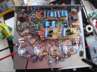
I just fired up my version of this amp for the first time with 6HJ5's and old Fisher outputs. Voltages are about as specified by millett, 41 mA through the outputtubes. I have a 39K anode resistor on the 6cb6 because I will attempt to bring up the B+ to 400 volt or so. No global NFB.
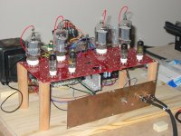
I made it P2P and it looks like a jungle or a Japanese city under the deck, but there is very little hum on one channel and none on the other channel. I use a different B+ regulator with dn2540 mosfet and 2 glow tubes in the 150V regulator.
The amp sounds really unbelievable good in the first minutes already. I will tweak it further and report later.
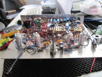
Another one born tonight with stock components, 6GV5 outputs and 6CB6 drivers. I'm waiting on iron from Edcor (the stock PM-100 Edcor set as specified by Pete plus two CXPP100-MS-4.2K for future experiments). I scavenged my Z565 dynaclone OPTs from my build of Eli's El Cheapo for now. They're 8k p-p rated at 17.5 Watts. They seem to hold their own. Low end seems well controlled except for the really low end. B+ is low at 220V. Using one 10 pounder wired with full wave bridge.
The amp does sound really good.
One issue though. Amp had been playing for about 10 minutes. I took the attached picture and then turned away from the amp to put the camera down. By the time I turned back towards the amp, I noticed the 6GV5 second from the left decided to turn into a glow tube 😱. I had the amp plugged into the wall (no kill switch) and as I frantically reached for the plug, the 2 amp fuse on the input side to the 10 pounder blew to save the day. Inspection of the board did not reveal any damage. Replaced the gassy 6GV5 with another and the amp played fine for the next hour.
Attachments
Last edited:
I made it P2P and it looks like a jungle or a Japanese city under the deck
I would like to see a picture please Jaap. Sounds like a daunting task.
I would like to see a picture please Jaap. Sounds like a daunting task.
Looks interesting, sounds great
Attachments
It appears that Mamak has posted 17 times this morning.
Are any of them on topic?
Has someone hacked into his account?
Is this worth investigating?
Andrew T.
Are any of them on topic?
Has someone hacked into his account?
Is this worth investigating?
Andrew T.

If i have a hot preamp source (i can push out up to 10vpp) can i stick with the stock 6CB6 drivers, or should i go with the higher gain 6GU5?
My thought was to stick with the 6cb6 and just up the gain on my preamp if i need to. But i dont know if the stock tubes can drive the 6hj5's to full output with the 600v b+ regardless of source voltage.
My thought was to stick with the 6cb6 and just up the gain on my preamp if i need to. But i dont know if the stock tubes can drive the 6hj5's to full output with the 600v b+ regardless of source voltage.
Yes, the 6CB6 can indeed drive the biggest of sweep tubes to 250 watts. I used them in all of my initial experiments that used an audio oscillator as a source. I only switched to the 6GU5 when I discovered that my CD player couldn't drive the amp to clipping. I noticed some reduction in distortion when switching to the 6GU5, but that may have been due to the fact that my 6CB6's were old and unknown and the 6GU5's were new and from the same batch.
6BD6
In "Glass Audio", volume 8, number2, 1996 writes Rickard Berglund about a single ended pentode amp with sweep tubes and pentode drivers.
Certain combinations of sweep tubes and pentode drivers are more effective in cancelling second harmonics than others.
Good combinations are for instance 6HJ5 (or E130L) + 6BD6; 6HF5 + 6BY7/EF85; 6LF6 + 6DA6/EF89.
Unfortunately he did not test the 6CB6.
I wonder if it is worth trying 6BD6 with the 6HJ5 in the PP red board.
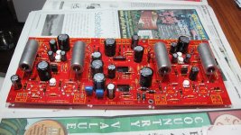
Woo its all coming together. Edcors are on order, mouser shipped, got caps, got sockets.
One question since this is my first tube pcb, tubelab seems to put a half components width in between the board and the component. Ive only done this in the past for ferrite beads, should I do this with this board for i assume heat disapation?
One question since this is my first tube pcb, tubelab seems to put a half components width in between the board and the component. Ive only done this in the past for ferrite beads, should I do this with this board for i assume heat disapation?
I personally would. There is quite a bit of heat radiating off the board. I also find it easier to take measurements when they are off the board a bit.Woo its all coming together. Edcors are on order, mouser shipped, got caps, got sockets.
One question since this is my first tube pcb, tubelab seems to put a half components width in between the board and the component. Ive only done this in the past for ferrite beads, should I do this with this board for i assume heat disapation?
tubelab seems to put a half components width in between the board and the component......should I do this with this board for i assume heat disapation?
Part of this habit comes from personal experience, part may be supperstition. I worked in TV, stereo and other consumer electronics repair through high school and for a few years after that. 1967 through 1973. I watched TV sets and stereos transition from PTP wired tube circuitry to PC board tube circuitry (Zenith was the last hold out with their "hand wired chassis") and finally to PC board mounted solid state. The early PC board designs had new failure mechanisms not seen in PTP wiring. Much of this was due to the junk phenolic PC boards used in the early sets, but we learned that components pulled down tight to the board often failed to an open, expecially radial leaded electrolytic caps. The PC board and its components in a vacuum tube design go through some serious thermal cycling in normal use. This can rip leads loose from the internal connections inside components over time. I must have changed dozens of cathode bypass caps in the vertical output section on late 60's Philco TV sets. They didn't go completely open, they became resistive or temperature sensitive leading to stretched out pictures.
PC boards have improved a great deal since the brown phenolic junk of the early 1960's. Components designed for PC board use have improved too. I used to recommend putting a piece of double stick tape on the bottom of radial electrolytics since we did this in TV sets to prevent callbacks. Notice that good quality caps now have a thick rubber base to allow for some thermal expansion and contraction. I would still allow for a small space between the cap and the PC board, 1/32 of an inch is good. The lead will get hot when it is soldered. It can grow by 1/32 of an inch during soldering. It will shrink as the solder cools putting the leads under stress form the beginning. I still don't like pulling the components tight to the PC board since the board itself will grow when hot and chances are that its thermal expansion characteristics are different than that of the components. You don't want the board pulling on the component leads.
Components like resistors will generate heat too. You want airflow all around the component to help shed this heat and avoid dumping it directly into the PC board.
PWR XFMR selection
Would not this transformer, connected as shown in the original post, provide the necessary current for the 6GU5/6HJ5 version of the amp, and use a second small transformer for the bias supply?
http://www.antekinc.com/pdf/AN-2T230.pdf
I have been neglecting this project for some time as I had been trying to determine how to assemble the chassis but have decided forget about that and just get it working and then focus on the aesthetics. So I have been taking cliff notes on some of Georges comments and other than the slight modifications to the circuit to allow the 6HJ5s to be used shown by Rknize, here is what I have come up with.
- Change 220k ohm schade feedback resistors(R29, 30, 31, 47) to 2-3 two watt resistors in series to handle the voltage spikes
-Change R48, 49 to 10k 3watt
-I had purchased a few of these mosfets a while back with the idea they would work with the red board. With a proper insulator and heatsink hopefully they will fit the bill to replace the specified mosfet for Q2. With a little careful work with my needlenose pliers I have the lead spacing worked out and I am able to place it on the board.
Link to item: 2SK3675-01
-create FWB for bias supply utilizing 44v secondary off of transformer
-Omit the 820pf capacitors C7, 9, 10, 15
Now for the power supply I have yet again drawn up another amateur attempt. There was some talk about using current limiting resistors after the bridge rectifier before the first cap. I would assume with these larger caps this will be essential. I do have a handful of CL90s in a box some where from my move.
Would not this transformer, connected as shown in the original post, provide the necessary current for the 6GU5/6HJ5 version of the amp, and use a second small transformer for the bias supply?
http://www.antekinc.com/pdf/AN-2T230.pdf
Would not this transformer, connected as shown in the original post, provide the necessary current for the 6GU5/6HJ5 version of the amp, and use a second small transformer for the bias supply?
I am not sure which original post you are referring to, but I have indeed run my board off of an Antek 2T-230 and a small 48 volt transformer for bias.
I plan to test my breadboard using the 10 pounder for the main power transformer, and that same Antek for the boost transfomer. The reason for doing this is to save space and weight. Its time to make a box for the amp and two 10 pounders + two OPT's is just too big for any of the sheet metal that I have.
I was referring to post #637 by nic6paul that shows the series connected secondaries after the 2 FW bridges.
Last edited:
That would be the exactly what I did. You would just need a bias transformer. That might be an interesting option and it would fit on my chassis nicely. The filament current capacity of that transformer might be a few amps shy although from what I remember these transformers have been known to be pretty robust.I was referring to post #637 by nic6paul that shows the series connected secondaries after the 2 FW bridges.
Last edited:
- Home
- Amplifiers
- Tubes / Valves
- Posted new P-P power amp design