What caps did you purchase?Hmm this is going to require some engineering. My PIO caps came, but they are 4" long and weigh 6oz, they are the same size as a el34. Im either going to have to mount upright or get creative on wiring the leads.
k75-10 hybrids. .22uf 1000v, they were only a few bucks more total vs the other pio styles. I figured id give them a shot since i already had an amp with VitaminQ's in it.
So George any more news on the above.I changed a few parts to fit what I had on hand, but there were two changes intended to boost the gain. I won't know how successful I was until I make some measurements. Pete specified 30K for the driver plate load resistors. I increased them to 39K in board #1. This definitely increased the gain but lowered the plate voltage. In board #3 I went to 43K and lowered the tube current by changing the 200 ohm resistor in the CCS to 270 ohms. I wouldn't recommend these changes just yet. The 10 pounder runs the board at a lower voltage than I used with all of my initial testing on board #1. It is also lower than in Petes design.
On another note I have had mine apart for a couple weeks now trying to build a chassis. I should have just left it on the board together. This chassis is much bigger than I anticipated. 40lbs in iron alone.🙄
So George any more news on the above.
On another note I have had mine apart for a couple weeks now trying to build a chassis. I should have just left it on the board together. This chassis is much bigger than I anticipated. 40lbs in iron alone.🙄
Hey, hey
A high iron to glass ratio is a good indicator of sonic merit! (A wise man once told me)
So George any more news on the above.
Due to a bunch of unexpected BS I have not been to my workbench in about 3 weeks. The breadboard amp that I made is still in the living room connected up to my speakers but I haven't been home much to listen to it. It sounds great, and MAY be a little more sensitive than the other one but I have not had time to measure it yet. Next weekend looks uncertain too.
6HJ5/6GU5
It appears as though the only change when using the 6HJ5/6GU5 combo, is the resistor change pictured in the photo at post #346. Is that correct? I think I remember reading about a grid resistor change but I did not make a note of the post #.
It appears as though the only change when using the 6HJ5/6GU5 combo, is the resistor change pictured in the photo at post #346. Is that correct? I think I remember reading about a grid resistor change but I did not make a note of the post #.
What resistance is being used for the output screen grid stoppers R8 and R11 with the bigger sweep tubes? I notice a substantial change in the plate curves for the bigger sweeps with the stock 1 K OHM resistor there. This may need optimizing. More like 100 Ohm maybe. But an FFT test at say 75% max power should be the final arbiter.
It appears as though the only change when using the 6HJ5/6GU5 combo, is the resistor change pictured in the photo at post #346. Is that correct? I think I remember reading about a grid resistor change but I did not make a note of the post #.
The latest is do the change as pictured, and reduce r21 to something like 1-2k or eliminate it, depending on how much b+ you are feeding it.
450v+ = stock ish
350v = 2k ish
300v = 1k ish
200v external tap= jumper.
R21 is designed to eat some of the 150+ volts the screen regulator has to drop to regulate to 150v, but it also limits the current too much at 100 watts out and causes the 150v screen to sag.
Last edited:
It appears as though the only change when using the 6HJ5/6GU5 combo, is the resistor change pictured in the photo at post #346. Is that correct? I think I remember reading about a grid resistor change but I did not make a note of the post #.
The resistor change pictured in post #346 is required to prevent blown parts. The board should work with only that modification but may not be optimum.
As mentioned reducing the value of R21 may be required. If you are using a "10 pound" power transformer to run the board your B+ will be in the 290 to 310 volt range. The drop across R21 may be too much to keep the screen grid supply in regulation. I have run my board with no resistor at all, but settled on a 1K 3 watt resistor for an easy screen current measurement, and a safety limiter. A blonde moment fried the resistor so that all of the color bands are now black but it still works and is still in the board.
What resistance is being used for the output screen grid stoppers R8 and R11 with the bigger sweep tubes?
I put 1K 1/4 watt carbon comp resistors in board #1 when I first built it, because that's what I had. It took me about 1 day to blow them up. I replaced them with 100 ohm 2 watt resistors. Board #2 has 510 ohm 1 watt resistors. It is the board that I have been listening to and I don't notice any anomalies. Board #3 has not been powered up yet.
I know with little transformers you can parallel the windings. Im not gutsy enough to do that with the b+ windings with recs, but what about heater windings when you are pushing 10 amps or more?
I was going to fire up the 2 transformers unloaded with 1 heater wire from each tied together, then measure the other 2 heater ends. If i get voltage then i got them out of phase, and i need to swap one set. Then i can just hook them to the board right?
PS edcor iron i ordered in feb is arriving tomorrow. Im half tempted to hook them up to my el84 setup i got right now🙂
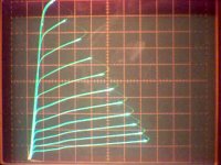
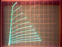
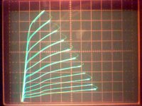
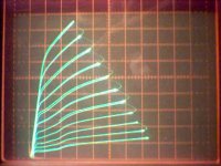
Here are the curves for the 6HJ5 (50V/div horiz., 50 mA/div vert., 2.2 V g1 steps, 115 V vg2) for a 0 Ohm, 120 Ohm, 480 Ohm, and 960 Ohm stopper on g2. One could play around with the value of the g2 stopper R to modify the harmonic dist. spectrum. But obviously the most power output, for a given screen voltage supply, will be with the lowest stopper value possible.
Attachments
but what about heater windings when you are pushing 10 amps or more?
Connecting two IDENTICAL windings in parallel is always possible and the total current capability is twice that of one winding.
Connecting two windings that are not identical in parallel is only possible if the rated voltage of the two windings is the same. Connecting windings of unequal voltage in parallel will usually lead to smoke! Assuming the voltages are equal (or very close) like the 10 pounder, the windings can be paralleled. The total current carying capability will usually NOT be equal to the sum of the individual winding current. It will be less because the currents will not share equally due to the differences in the winding resistances. It will always be greater than the capability of the biggest winding. In the case of the 10 pounder running the red board with 6HJ5's you can connect all of the heater windings in parallel.
You are right about the phasing. Get it right and it works, get it wrong and it smokes. The big 6.3 volt winding has enough current to burn out one of the little ones. The method you describe with the voltmeter is good and reasonably safe. Just be sure to tape up or otherwise avoid the HV winding while measuring.
You can also connect a small light bulb (40 watt 120 volt) in series with the primary, power up and note the bulb brightness (dim or unlit) then take your best guess with the secondaries, and test again. If it lights up bright, it's wrong. Test until you have all windings paralleled with no glow.
With the windings paralleled, connect the bundles to the normal heater terminals on the board. Connect the single center tap to the center tap terminal.
If you are using a transformer without a CT like an Antek, run a jumper from the CT terminal of the board to one of the heater terminals on the board. It's only purpose is to elevate the heater supply a few volts positive to prevent hum.
How offboard do you think i can get away with for the coupling caps. I can only seem to fit them under the output transformers right now. Since it is in the balanced section I thought that would work due to the noise cancellation. If i really had to i could even use shielded cable but i think that might be over kill.
Man I got my edcor's, I put all my iron in a box, the box weighed 44lbs (20kg). Thats not counting the board, tubes, top plate. I dont think I can make a wooden chassis that will support this weight, and if I do the chassis will weigh over 10lbs with good bracing, and I dont think I can carry a 60 pounds with one hand, or 2 handed at chest level. Hmm I wonder how much a guitar strap can take...
Put some casters on it and roll it 😱Man I got my edcor's, I put all my iron in a box, the box weighed 44lbs (20kg). Thats not counting the board, tubes, top plate. I dont think I can make a wooden chassis that will support this weight, and if I do the chassis will weigh over 10lbs with good bracing, and I dont think I can carry a 60 pounds with one hand, or 2 handed at chest level. Hmm I wonder how much a guitar strap can take...
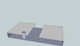
For mounting your giant capacitors how about creating a mounting platform that is secured to the mounting holes on the board via some standoffs. It is a bit hard to explain. If you used something like a 1" nylon standoff you will probably have to cut some holes in the board to allow the electrolytic caps to stick through. Perhaps some vent holes as well. The picture is pretty bad, I did it in about 30 seconds. But I was thinking you could leave the middle portion of the board open where the fets are. Use two boards on either side secured by bolts from each of the 10 mounting holes.
Attachments
I do not use global feedback and have tied the grid of one of the 6CB6 tubes directly to earth with a 1K cc resistor. I also see a 3K3 resistor (R68) in the schematic in series with this 1K resistor (grid stopper I suppose) connected to ground.
Mij question: Is the value of the resistor from grid to ground critical ?
Mij question: Is the value of the resistor from grid to ground critical ?
Mij question: Is the value of the resistor from grid to ground critical ?
No, anything will work from a dead short up to tens of K ohms. The 1 K is a stopper. The 3.3K is part of the feedback divider.
I found out years ago that a 1 meg resistor will not work since Miller will couple a voltage onto the grid and screw up the HF response.
Hello,
Has anyone built this red board amplifier with 807’s or 1625’s?
Results?
DT
All just for fun!
Has anyone built this red board amplifier with 807’s or 1625’s?
Results?
DT
All just for fun!
Novice level grounding question since I have never built anything electrical ever.
http://www.pmillett.com/images/DCPP_inside.JPG
I am planning to make 100% stock version as seen on pmillett.com(see the pic) with only exception of using 6GV5 . So in here I see one green wire running from the PCB to IEC's ground and a wire running from each channel's speaker binding post ground to the PCB. So all together 3 ground wires as seen in the picture and all the grounding is done? or there's more to be done to ground this amp?
There is earth that runs from the iec to earth ground. This is to keep you from killing yourself should the amp fault and the top plate go hot. It is the green wire that goes from the iec to ac ground, which connects to the top plate via the screw right next to it
there is audio ground, which is both speakers,rca's,and the power transformer connect to. This does not connect to the top plate nor to earth.
then there is the ground loop isolator that connects the audio ground to the top plate. It is in the front of the amp and is the 4 huge diodes. It connects to the top plate via the screw next to it.
So to sum it up;
earth connects to top plate for safety
audio ground connects to only audio stuff
ground loop isolator connects audio ground to earth via the top plate.

- Home
- Amplifiers
- Tubes / Valves
- Posted new P-P power amp design