That is interesting. I may have to measure mine as I have installed a 4.7k in R21. Perhaps after work tomorrow I will have some time to play around with my board. I have the two layer chassis built up for the most part minus some holes here and there I need to make and fit the front panel. I don't see this amp being boxed up anytime soon though.
I plugged in the second power transformer, reset the bias and cranked it up. When both channels are driven hard the power instantly rises to the expected 125 WPC, then folds back to about 100WPC.
Measure the voltage at the output side of the resistor at the junction of the resistor and the mosfet. The voltage is about 280 with no signal and drops to 130 when the amp is cranked hard.
No pictures now. Micro$haft installed updates yesterday and now Vista won't recognize the CF card without a reboot. They think if they update Vista until it doesn't work any more I'll buy 7.....not happening....I'll put XP back.
More experiments tomorrow.
The 6GY5 will drop right into this board. The 16GY5 has a 15 volt heater and it is wired in parallel with the 6CB6's. Since there is no 16CB6 you will need to cut the PC board trace and wire the heaters seperately.
That's ok, I bought chassis sockets anyway so will wire the 15v heater separately. No cutting in my board (at least for now)
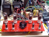
I replaced the 4.7K resistor with a 2.5K resistor and the amp now cranks out 125WPC. The screen voltage holds a steady 147 volts from no power to full power.
The B+ voltage is lower than the last board, using the same tubes and transformers, but it has been very hot and everybodies AC units are humming. It is also dinner time. 600 volts at idle, 560 volts at 250 watts out.
I also made some changes to boost the gain and get the driver plate voltage up to 135 volts with 6GU5's. Time to hook up some speakers and crank it!
Billy granted me permission to see my pictures from last night.
Attachments
Sounds very interesting. I would be curious to hear how your listening sessions go.....although I am sure it will be LOUD. I have a second red board that I plan to populate here in the future to play around with a few different tubes I purchased. I have enough iron for the power supply, just trying to find a decent set of OPTs that won't break the bank 🙂I replaced the 4.7K resistor with a 2.5K resistor and the amp now cranks out 125WPC. The screen voltage holds a steady 147 volts from no power to full power.
The B+ voltage is lower than the last board, using the same tubes and transformers, but it has been very hot and everybodies AC units are humming. It is also dinner time. 600 volts at idle, 560 volts at 250 watts out.
I also made some changes to boost the gain and get the driver plate voltage up to 135 volts with 6GU5's. Time to hook up some speakers and crank it!
Billy granted me permission to see my pictures from last night.
I plan to fire my board up tonight and measure the voltages. I "think" I might have a resistor that I can parallel with r21 to bring that value down a bit. Hopefully my neighbor isn't home yet. I don't feel like having her knocking my door down!
I would be curious to hear how your listening sessions go.....although I am sure it will be LOUD.
LOUD was putting it mildly. I just achieved a new personal best. A turn it down call from 1200 miles away! It seems that the lady that lives across the street was taking her evening nap when I dimed some Linkin Park. She called the house phone a few times without success, so she called my wife in West Virginia who called my cell phone which was set on vibrate in my pocket.
I played this amp for an hour at full volume. Disturbed and Linkin Park could provoke some audible distortion. I don't know if it was clipping, OPT saturation, or speaker Xmax limitations, but it was extremely loud. Most of my other CD's were loud with no trace of distortion. Dave Brubeck was comfortably loud, but it is a quiet CD. I think the amp still needs more gain.
I will have to make sensitivity measurements on this amp and board #1 to see if my changes made any difference. It seems louder, but it's still not enough. I am not sure you can get to the point where clipping can be reached on all CD's without another stage, but that is what board #1 is for.
#2 passed the burn in test without burning out, so now its time to make a pretty box for it. #3 will be reserved for the results of some experiments on #1. I am itching to feed it some DH pentodes.
I have enough iron for the power supply, just trying to find a decent set of OPTs that won't break the bank
I am amazed at the sound and power that comes through these little OPT's with this board. I have seen them saturate with a Simple P-P at 25 WPC. I saw a perfect 40 Hz sine wave flowing out of this amp tonight at 80 WPC. The distortion was 3%. They are guitar amp OPT's made for 6600 ohms, but I am running them at 3300 ohms by putting my speakers on the 16 ohm tap. One of the experiments I am going to try is to see if running 2 OPT's in parallel will make even more power.
What modifications to Pete's original design did you perform?LOUD was putting it mildly. I just achieved a new personal best. A turn it down call from 1200 miles away! It seems that the lady that lives across the street was taking her evening nap when I dimed some Linkin Park. She called the house phone a few times without success, so she called my wife in West Virginia who called my cell phone which was set on vibrate in my pocket.
I played this amp for an hour at full volume. Disturbed and Linkin Park could provoke some audible distortion. I don't know if it was clipping, OPT saturation, or speaker Xmax limitations, but it was extremely loud. Most of my other CD's were loud with no trace of distortion. Dave Brubeck was comfortably loud, but it is a quiet CD. I think the amp still needs more gain.
I will have to make sensitivity measurements on this amp and board #1 to see if my changes made any difference. It seems louder, but it's still not enough. I am not sure you can get to the point where clipping can be reached on all CD's without another stage, but that is what board #1 is for.
#2 passed the burn in test without burning out, so now its time to make a pretty box for it. #3 will be reserved for the results of some experiments on #1. I am itching to feed it some DH pentodes.
Linkin Park...now there is a band I haven't played in a while. I may have to dig out their cds. Rage Agains the Machine is another one I need to find.
I have a set of these on my Simple PP which I really enjoy as is. I don't think I can get myself to steal these from that amp 😉 I may have to troll ebay looking for a deal. I have seen a few decent sets go here and there. Usually I lose out in the last few seconds due to the snipers......perhaps I need to start sniping as well 😀I am amazed at the sound and power that comes through these little OPT's with this board. I have seen them saturate with a Simple P-P at 25 WPC. I saw a perfect 40 Hz sine wave flowing out of this amp tonight at 80 WPC. The distortion was 3%. They are guitar amp OPT's made for 6600 ohms, but I am running them at 3300 ohms by putting my speakers on the 16 ohm tap. One of the experiments I am going to try is to see if running 2 OPT's in parallel will make even more power
Last edited:
What modifications to Pete's original design did you perform?
I changed a few parts to fit what I had on hand, but there were two changes intended to boost the gain. I won't know how successful I was until I make some measurements. Pete specified 30K for the driver plate load resistors. I increased them to 39K in board #1. This definitely increased the gain but lowered the plate voltage. In board #3 I went to 43K and lowered the tube current by changing the 200 ohm resistor in the CCS to 270 ohms. I wouldn't recommend these changes just yet. The 10 pounder runs the board at a lower voltage than I used with all of my initial testing on board #1. It is also lower than in Petes design.
There are several interacting factors in this circuit to determing the driver gain. Substituting a tube with higher trasnconductance (the 6GU5) is a start. Increasing the plate load resistor raises the gain, lowers the plate voltage, and increases the amount of "Schade" feedback. Increasing the Schade resistor will bring the feedback down, but lowers the plate voltage again. Lowering the tube current will bring the plate voltage back up, but lowers the transconductance a bit. There are a lot of variables here and I haven't found the magic combination yet. There are a few other experiments that I can try now that I am not afraid of blowing up board #1.
I have a set of these on my Simple PP which I really enjoy as is.
I have 3 Simple P-P's. All use these transformers. I bought about 100 of them about 15 years ago from an Ebay seller. Most went into guitar amps. I have cranked about 150 watts through them in a guitar amp without failure. I did blow one up by operating the amp without a load. Flames and smoke shot out of the side! Note there are two flavors of these transformers from several vendors. These were made by Schumaker (same as the 10 pounders). These are 6600 ohms. THere was also a 4400 ohm version. Both used to be common on Ebay but I haven't seen them lately.
"The 10 pounder runs the board at a lower voltage than I used with all of my initial testing on board #1. It is also lower than in Petes design.
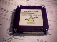
You could get 360 V regulated out of the 10 pounder by using one of these:
(got it on EvilBay for $30, rated for 500 Watts! There's a 1000 Watt one too.)
Oh, and found a tube (17.5 watt, octal though) that is cheap and might be of interest to try on the board: 12GC6
You could get 360 V regulated out of the 10 pounder by using one of these:
(got it on EvilBay for $30, rated for 500 Watts! There's a 1000 Watt one too.)
Oh, and found a tube (17.5 watt, octal though) that is cheap and might be of interest to try on the board: 12GC6
Attachments
Last edited:
OK, you got me curious, but I can't find it. Got a link or a clue what to search for. I have tried everything I see on the unit. I am guessing that this is not an isolated supply. You must use a transformer and you must know what you are doing to avoid frying yourself.
It was a buy it now deal from a few months ago. Hopefully more will show up some time. I got one of the 1000 Watt modules last Spring for $25. I hadn't really been looking actually, it just showed up in a search for a Lambda power supply I was looking for. No idea how often they show up. They aren't isolated, have to use some kind of isolation xfmr, 100 VAC to 240 VAC input range. They are PFC, or power factor corrector front ends for a power supply (a boost converter). They draw current proportional to instant AC voltage, so look like a resistive load on the power line. But they also regulate to the 360 V output, very convenient. They can be bought new, but are around $150 I think. It's a Lambda PF500-360. I think the new units are PF500-360A, just a control mod for on/off sequencing with their DC/DC modules.
OH, takes a couple capacitors on the input (after the rectifier in the unit) and output and a resistor or thermistor for soft start. Fairly simple to set up. An input filter module is also recommended too since it is a switching unit. They make a custom module, but a surplus Corcom line filter works fine.
Vicor makes a similar 260 VDC unit (off of 120 VAC), called VICOR-HAM or HAMD module, but I haven't found one of them yet.
Last edited:
I replaced the 4.7K resistor with a 2.5K resistor and the amp now cranks out 125WPC. The screen voltage holds a steady 147 volts from no power to full power.
I was using the stock resistor as well. This resistor got quite stinky from having to dissipate nearly 2x what it was rated for. However, I was running ~475V to the PCB whereas you are running far less voltage. I saw a lot of sag, but the screen supply stayed in regulation IIRC.
LOUD was putting it mildly. I just achieved a new personal best.
LOL. At times I've had 3 sets of speakers going full tilt on three different amps. I've wondered if I'd get a visit from the neighbors, but you really can't hear much outside if there aren't any windows or doors open. My house is 65 years old and made of brick, so I imagine that has a lot to do with it. Plus, all the speakers were in the basement.
They can be bought new, but are around $150 I think.
There are several low voltage versions listed now, but they are in the $100+ range.
but you really can't hear much outside if there aren't any windows or doors open.
I had the amp hooked up to the Silver Iris OB speakers since thay can eat all that this amp can give. These speakers have a very strange property of making sound appear. It is loud inside the house. It is not too loud outside in the yard, and audible in the street and the yard across the street. However the bass is quite loud inside the house across the street, even if all the windows are closed which was the case today. It was 80 degrees when I got home from work at 6:30 PM.
It was a buy it now deal from a few months ago. Hopefully more will show up some time. I got one of the 1000 Watt modules last Spring for $25. I hadn't really been looking actually, it just showed up in a search for a Lambda power supply I was looking for. No idea how often they show up. They aren't isolated, have to use some kind of isolation xfmr, 100 VAC to 240 VAC input range. They are PFC, or power factor corrector front ends for a power supply (a boost converter). They draw current proportional to instant AC voltage, so look like a resistive load on the power line. But they also regulate to the 360 V output, very convenient. They can be bought new, but are around $150 I think. It's a Lambda PF500-360. I think the new units are PF500-360A, just a control mod for on/off sequencing with their DC/DC modules.
OH, takes a couple capacitors on the input (after the rectifier in the unit) and output and a resistor or thermistor for soft start. Fairly simple to set up. An input filter module is also recommended too since it is a switching unit. They make a custom module, but a surplus Corcom line filter works fine.
Vicor makes a similar 260 VDC unit (off of 120 VAC), called VICOR-HAM or HAMD module, but I haven't found one of them yet.
Because PFC draws current proportional to voltage, the output always has
the full 120Hz ripple plus the switching (only avg voltage will be regulated).
Still need LC filter afterward capable of smoothing 120Hz and filling the gaps.
If you dump the PFC straight into a big cap without any L, its just a boost
regulator with no power factor correction if it still works at all...
Unless your PFC isolates. Or after LC, gets chopped again and isolated.
I don't see how you get out of all the same sized lumps of 60Hz iron???
I've not tested any PFCs yet that isolate (not sayin they don't exist),
Assumption that some further stage will always handle that function?
Safety transformers at TI's high voltage lab at least a two man lift.
Higher ups don't trust me above 63V in my own lab.
Last edited:
The user manual for the PFC units only uses a big electrolytic cap after the unit before the DC/DC converter. But then the DC/DC converter can fix the cap V droop during the AC dropout times. So an added inductor - cap filter would be needed for our purposes. Should be much smaller ripple here than the usual xfmr - rectifier combo though, since the PFC is able to charge the cap over a larger % of the cycle time.
Another approach (particularly for less than 500 Watts) would be to connect a small cap after the bridge rectifier in the unit, so that the PFC converter would never see a zero volt input. The cover is removable on these and the rectifier is easily accessed.
Another approach (particularly for less than 500 Watts) would be to connect a small cap after the bridge rectifier in the unit, so that the PFC converter would never see a zero volt input. The cover is removable on these and the rectifier is easily accessed.
PFC could pump a ripply current onto a constant voltage cap.
Not sure what mental defect I thought a choke was essential?
Yet something L or C has to store energy to ride out deadtime.
PFC prevents itself from drawing amps when involtage dips low.
Almost opposite you might expect of a simple boost regulator.
PFC deliberately won't prop up deadtime so much as pure boost.
Normal switchers have negative resistance slope at the input.
More Voltage= less Amperes , Less Voltage = more Amperes.
PFC is somehow smart enough to do the opposite. They keep
the resistance slope positive, and in phase...
Last edited:
Arghh! The bridge rectifier is readily accessible on the 1000 Watt model, but the 500 Watt model has it stuffed between two PC boards 1/4 inch apart. Can reach the neg. bridge terminal easily, but the positive bridge terminal is 1/2 inch in from the edge with some plastic spacer in the way. Might be able to solder to it with a long thin soldering tip.
Can always just put another bridge rect. in front of the PFC module with a small cap across that, then in to the PFC. But nicer to avoid the extra bridge diode drops if possible.
Can always just put another bridge rect. in front of the PFC module with a small cap across that, then in to the PFC. But nicer to avoid the extra bridge diode drops if possible.
Attachments
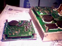
Turned out to be easier to connect up the aux cap connections to the PFC bridge rectifier than I expected. I just used "precision" surgical technique (a small Rat Shack soldering iron with a #14 copper house wire tip, custom bent up to form the soldering tip in just the right way) to reach in and solder the recessed terminal. The easy to reach neg. terminal proved to be the harder one to solder since it had some silicon glue on it. Then a couple of small holes thru the case completes the job. TFE covered leads.
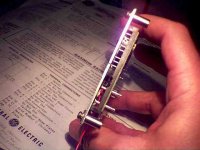
Have to determine what minimum size cap works to keep it in continuous mode operation with the specified load now. I'm guessing a 1 uF/600V mylar cap will be sufficient to eliminate the ripple glitch. The 360 VDC output should look like a linear regulator output now. Well, I'll put some ferrite filter beads on the output too, a common mode ferrite choke too. A second big electrolytic at the OT CT too.
Have to determine what minimum size cap works to keep it in continuous mode operation with the specified load now. I'm guessing a 1 uF/600V mylar cap will be sufficient to eliminate the ripple glitch. The 360 VDC output should look like a linear regulator output now. Well, I'll put some ferrite filter beads on the output too, a common mode ferrite choke too. A second big electrolytic at the OT CT too.
Attachments
Last edited:
"I've not tested any PFCs yet that isolate (not sayin they don't exist),
Assumption that some further stage will always handle that function?"
All the PFC designs that I'm aware of are NON isolating, although it should be possible to design one at increased expense. (would be a nice product for tube audio) The place where I see these as being most useful is for a Circlotron or Elliptron amplifier where two floating B+ supplies are needed. I got some Stancor TGC175-230 split bobbin xfmrs (175 Watt, 2*120 V to 2*120V, just 67 pF common mode capacitance) to use this way. (Triad, Magnetek, Hammond, .... all make similar)
Trying to make two floating, regulated, B+ supplies the usual way with very low common mode pF capacitance would be too much of a headache. And the usual switching supplies have high capacitance between input and output and ground. (but could be run through the same split bobbin isolation xfmr, seems a bit redundant/silly though)
The PFC units are a good match for the 10 lb boat anchors if you just want 360 VDC regulated.
Even at the $150 new price, they are about the same or less than the usual tube iron. But for surplus iron, well, have to go surplus PFC to compete.
Oh, yeah. I forgot to mention that these modules provide a remote turn on logic level input for delayed B+ power up (as well as standard soft start). Could be quite usefull too. (They have an SCR in them that can turn on the DC output, but not turn it off without power removal)
Last edited:
- Home
- Amplifiers
- Tubes / Valves
- Posted new P-P power amp design