I've realized that there is something about the power supply that I cant' figure out.
The B+ ripple filter and the G2 regulator have a similar topology except for the string of zener diodes D5 D7 D8 in the G@ regulator and the 1 meg resistor in the B+ filter. I can understand this.
However I don't understand why R33 is 470K and R56 is 47K. I presume it is because the B+ current is much greater than the current for the G2 regulator.
My real question is why the 470K is not 500K or 200K or 100K. Is there a formula at work here that includes current as one of the elements?
ray
If you look at it in terms of a voltage divider, it makes more sense. The diode chain is holding the FET gate at 150V and is being pulled up by the 470k. If you do the math (assuming the PSU is putting out ~380V), R33 has to drop 230 volts. The divider in the ripple filter holds the gate at ~95% of B+, so the 47k only has to drop ~18V. The math works out for both so that the circuit driving the gate voltage has about 0.3-0.5mA running through it. You have to be mindful of dissipation, so it pays to keep the current low. Using a FET makes this easier.
George, when you next whip out the old red board I would be very interested if you could establish some reference data for the 6GY5's you bought recently. That would be very helpful for me in choosing transformers. Thank you.
George, when you next whip out the old red board I would be very interested if you could establish some reference data for the 6GY5's
I plan to light up some tubes this weekend.
I noticed something a little odd today when I installed a new set of 6GU5s. After some listening I decided to check the driver balance The plate voltage was around 90volts for all the tubes on the rdp1/rdp2 and ldp1/ldp2 test points. Everything sounded just fine and Disturbed was playing for quite some time 🙂 So I just wanted to see that I wasn't imagining things I put the 6dk6s back in and plate voltages came back up to 130volts. Does anyone know why I would be getting such a variation?
Last edited:
Does anyone know why I would be getting such a variation?
The CCS in the tail of the input stage will force the cathode current to 8.5 mA through each tube (given on Petes schematic). The plate current is given as 6.8 mA leaving a screen current of 1.7 mA. 6.8 mA through the 30K plate load resistor and the 1K decoupling resistor should drop about 200 volts. Given Petes B+ of 335 volts we should have about 135 volts on the plate.
The data sheet I have for the 6CB6A has curves for a screen voltage of 125 volts, so I am guessing from those curves. It looks like for a grid voltage of -2 volts the numbers agree with what Pete shows on his schematic. Our B+ is now a bit lower than 335 volts so the plate voltage will be a bit lower.
I have no curves for the 6GU5 but we can infer a lot from the characteristics data. The CCS will still force 8.5 mA through each tube. The characteristics are given for a plate current of 9 mA, look at the screen current. It is 0.25 mA. This means that nearly all of the cathode current goes to the plate, so 8.5 mA of cathode current equals about 8.3 mA of plate current. Now with 8.3 mA flowing through the 30K plate load, the drop will be 250 volts. With Petes original B+ of 335 volts we now have 85 volts on the plate. With our lower B+ we get even less.
So the 6GU5 will bring the plate voltage down. I discussed this back a few dozen posts. THere are several ways to bring the voltage back up. Each has its pro's and con's and I will experiment further after I have more than 1 board to play with. I would like to add more gain and get the voltage up a bit too, but these are conflicting variables.
I am using a 39K plate load resistor which makes things even worse, but the amp doean't distort even when hammered. I find that most CD's can't push this version to clipping, but it is loud. Disturbed (ten thousand fists) doesn't get to clipping, and isn't as loud as some of my other CD's. When driven by an audio oscillator the output stage clips first, so the low plate voltage doesn't seem to be an issue.
Do the 6GU5's make your amp louder?
Ahh I must have missed that post. I have been slowly reading Morgan Jone's book on my breaks at work. So it has been going slow. I think half the problem with my low volume was the DVD player I was using. I switched to a usb powered DAC I built a while ago to use with my Macbook and the difference is night and day. I have never heard "Inside the Fire" this loud in my house The 6GU5s have made a difference as well. Thankfully my neighbor in the townhome next to me is a bit forgiving considering I snow blow her driveway out when it snows.
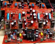
I don't think it's big enough to come from a slot 1. It came from the box where all chips go to die and shed their skin. Most are from the 486 / Pentium 1 era. Board #2 just got outfitted with a TO-3 heatsink robbed from a mainframe computer card. I should fire this board up sometime tonight. Once it is working it will take the place of board #1 in my amplifier so that the amp still works, and a nice chassis can be built for it. Board #1 will go back to life as a lab rat. Board #3 will be saved for something different. Exactly what depends on the results of some upcomming experiments.
Attachments

You know looking at all this im not sure if im ready for the ubber version just yet.
If i make a stock one, with 1 10pounder (i think 310v B+) with all the stock parts, and use 6HJ5's (they seem to cost as much as stock), and like a 3k primary, you think i can get output comparable to a EL34pp setup?
I figure with the 6hj5's i can go down to 3k primaries, which should get me like 40 watts or so?
I have some computer heatsinks from the pentium 1 age somewhere, thought they'd come in handy sometime.
Seeing your three boards made me think about mine sitting here unpopulated sofar. So I started to look at the BOM again and copied into Mouser website. Works great and fast. Only thing is that the Ixys part is not available for sale in my area?
Can you confirm whether I could follow the 6GV5 setup/BOM for my 16GY5, pinout seems to be the same.
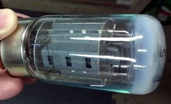
Picked up my 26LW6s today. Starting to get psyched.
Where can I get room size sheets of plastic like George uses to stand behind while turning the amp on? LOL.
Where can I get room size sheets of plastic like George uses to stand behind while turning the amp on? LOL.
If i make a stock one, with 1 10pounder (i think 310v B+) with all the stock parts, and use 6HJ5's
You need to modify the rectifier circuits to use the 10 pounder. Petes circuit works with a transformer that has a center tap. The 10 pounder has no center tap. No board modifications are needed, you need to add 4 more diodes to the back of the board. I'll post the pictures of my sky wired diodes. If you even think that you are going to add "boost" later I recommend using 3 amp diodes for the B+ circuit. They are a bit bigger and don't fit the holes in the board, but can be made to work. The 1 amp diodes are marginal for high powered applications. Other than the diodes my boards are built using Petes parts list. I made a few changes but they were to fit parts I already had. When it's time to turn things up you don't need to jump all the way to two 10 pounders. A smaller boost transformer is possible and that is what the third board is for! I now have 1 set of high efficiency speakers and a second set is under construction. I don't need more than 250 watts, so I am exploring some new ground for the shiny red board.
I figure with the 6hj5's i can go down to 3k primaries, which should get me like 40 watts or so?
The B+ is about 300 volts with one 10 pounder. I can fire my new board up on one transformer and see what I get out of it. I am using 3300 ohms. Thats probably the smart thing to do. That way the fire and smoke cloud will be smaller!
Where can I get room size sheets of plastic like George uses to stand behind while turning the amp on? LOL.
I'm sure that they can be purchased for large sums of cash. I picked that one up out of the street after a hurricane passed through. It's all scratched up but the price was right.
Only thing is that the Ixys part is not available for sale in my area?
I don't know what's up with IXYS. They don't like to sell chips? I haven't tried it yet in the red board, but the Supertex DN2540 in the TO220 package works in my Tubelab boards in place of the IXYS. The 200 ohm resistor will need to be tweaked to get the right current.
Can you confirm whether I could follow the 6GV5 setup/BOM for my 16GY5, pinout seems to be the same.
The 6GY5 will drop right into this board. The 16GY5 has a 15 volt heater and it is wired in parallel with the 6CB6's. Since there is no 16CB6 you will need to cut the PC board trace and wire the heaters seperately.
Picked up my 26LW6s today. Starting to get psyched.
The 'LW6 is one of my favorite sweep tubes. There are several versions from big to flippin huge. Oddly enough I have not tried them in this board yet. Too many tubes, not enough time.
Found these at mouser: vishay 625-SRP300K-E3
Vishay 625-SRP300K-E3
800v(stock is 1000v) 200ns(half as fast) 3amp
Its Bigger: .050" lead, .35" body, vs stock .030" lead, .20" body.
Vishay 625-SRP300K-E3
800v(stock is 1000v) 200ns(half as fast) 3amp
Its Bigger: .050" lead, .35" body, vs stock .030" lead, .20" body.
When I was running the board from the bench supply I saw the current meter up close to 1 amp with the 6HJ5's and well above 1 amp with 35LR6's. I decided that 1 amp diodes might blow, especially when I hook up the BAC's that I finally found. Blown diodes make the transformer unhappy.
I used Vishay UF5408 for the B+ and boost rectifiers, Mouser # 625-UF5408-E3/73. I used Vishay UF4007 for the bias rectifiers, Mouser # 625-UF4007-E3/73. They worked fine in board #1 so they went into #2 and #3. The pins on the 3 amp diodes are too fat to fit the holes in the board. I cut the leads at an angle leaving a sharp point. I bent the leads so the diodes set in the holes on the points, then soldered. All 3 boards are done this way. #1 has been alive for over a month now. I haven't had to touch it until Sherri came home and I had to hide it. It will now be dismantled for a board transplant.
Let the surgery begin.
I must bring up something that I found during the build of these two boards. I did not notice this during the build of the first board since I never imagined the extremes that this board could handle.
The resistor R30 is one of the Schade feedback resistors and it is connected to the plate of one of the output tubes. The resistor R15 is a cathode resistor and it is connected to ground. The plate pin of R30 and the ground pin of R15 are very close together. Under extreme conditions there could be 1300 volts peak on the plate pin. When assembling the board make sure that the leads are clipped close and the ends are well seperated. Make sure that this area of the board is clean. Excess flux can absorb moisture and lead to fireworks. I have not seen an issue at the 125 WPC level, and 250 WPC was tested for short periods of time.
The resistor R30 is one of the Schade feedback resistors and it is connected to the plate of one of the output tubes. The resistor R15 is a cathode resistor and it is connected to ground. The plate pin of R30 and the ground pin of R15 are very close together. Under extreme conditions there could be 1300 volts peak on the plate pin. When assembling the board make sure that the leads are clipped close and the ends are well seperated. Make sure that this area of the board is clean. Excess flux can absorb moisture and lead to fireworks. I have not seen an issue at the 125 WPC level, and 250 WPC was tested for short periods of time.
If i make a stock one, with 1 10pounder (i think 310v B+) with all the stock parts,...I figure with the 6hj5's i can go down to 3k primaries, which should get me like 40 watts or so?
I fired up my board and ......uh it didn't work. I found the diode that I put in backwards, turned it around and it works.
Using one 10 pounder and a 3300 ohm load I get 38 watts per channel, so 40 WPC with a 3K load is probably about right.
I found another issue that I have seen before. I built the board with the recommended 4.7K 5 watt resistor for R21. This causes the screen voltage to drop when the output power goes above 25 WPC. Board #1 has a 1K 3 watt resistor. The screen current usually goes down when the plate voltage goes up, so I will measure again when I plug in the second transformer.
- Home
- Amplifiers
- Tubes / Valves
- Posted new P-P power amp design