"I was thinking 5k at the time but had already realized that given the 50V proviso I've mentioned, I was only going to get 98W or so, not counting various and sundry voltage drops. The next step down from 5k in Edcor-land is 3.5k. No LOL, just compromise, as in just about any engineering enterprise. I'd much rather over-design a bit than under-design."
I'm laughing because I went back and forth for a while between 5K and 4K2. I'll probably want to try the 4K2 also but I'll probably be happy with 90W out. My B+ power supply delivers about 575V under load but I'm using 6550s (which have about the same gm as the 6LR6 so the load lines end up pretty much the same but for Vg2).
The other consideration is the plate dissipation, but for an audio amp it won't be driven continuously at high power levels so the loadline can be a little steep without causing any harm.
I'm sorry for second-guessing your choice. The voltage just sounded a little high for 3K3. The 4K2 sounds like a great happy medium.
George,
I forgot about the 6LW6; don't see too many of those monsters around. They all have the same 40W data sheet rating FWIW.
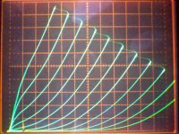
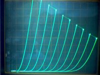
I took some pics of the 6HJ5 in Schade mode on the curve tracer. (Someone requested these in another thread. Likely some interest here too.) There was no cap in the Rfdbk path, so the 0V step and a few after are actually running the grid positive due to the R divider directly from the plate.
A: 6HJ5 Schade 50 mA/div Vertical, 20 V/div Horiz., 123V on g2, 5 V steps, 124K Rfdbk, 20.66K Rinput
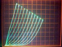
B: 6HJ5 Schade 50 mA/div Vert., 20 V/div Horiz., 123V on g2, 5 V steps, 62K Rfdbk, 20.66K Rin
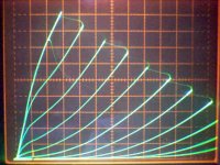
C: 6HJ5 Schade 50 mA/div Vert., 20 V/div Horiz., 123 V on g2, 5 V steps, 186K Rfdbk, 20.66K Rin
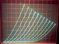
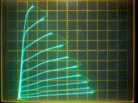
D: 6HJ5 actual triode configured, 50 mA/div Vert., 20 V/div Horiz., 3.8 V steps g1
E: 6HJ5 actual triode configured, 10 mA/div Vert., 20 v/div Horiz., ? steps g1 probably 2.4 V
A: 6HJ5 Schade 50 mA/div Vertical, 20 V/div Horiz., 123V on g2, 5 V steps, 124K Rfdbk, 20.66K Rinput
B: 6HJ5 Schade 50 mA/div Vert., 20 V/div Horiz., 123V on g2, 5 V steps, 62K Rfdbk, 20.66K Rin
C: 6HJ5 Schade 50 mA/div Vert., 20 V/div Horiz., 123 V on g2, 5 V steps, 186K Rfdbk, 20.66K Rin
D: 6HJ5 actual triode configured, 50 mA/div Vert., 20 V/div Horiz., 3.8 V steps g1
E: 6HJ5 actual triode configured, 10 mA/div Vert., 20 v/div Horiz., ? steps g1 probably 2.4 V
Attachments
Last edited:
I have been at work every day since July 4th, usually for 12 hours a day. My board layout is finally done, so I didn't have to go to work today. I had a few hours and the red board is still in the hot seat, so I decided to play with it. I have already stuffed it with some big tubes and taken it to the end of the knob on my power supply, so what's left to do.
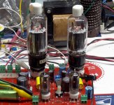
I have received a few requests to test some octal tubes. In fact one forum member even sent me some to test, so I wired in a pair of octal sockets and plugged it a pair of 6DQ5's. Assuming that they aren't much different than most other 24 watt sweep tubes, I was assuming that 550 volts and 3300 ohms would net 100 watts.
So I wired a pair of 6DQ5's into the red board, set the screen supply at 150, the plate supply at 550, and adjusted the bias current for 30 mA. I applied enough signal to get 1 watt and tweaked the bias current and the balance for minimum distortion. 0.37% distortion comes at 33 mA and more or less current raises the distortion although it remains under 0.5% from 27 to 50 mA.
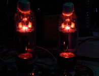
I then applied more crank. As the input signal went up, so does the output power and the distortion. 50 watts makes 1.89%. 100 watts gives 3.27%. I usually state amplifier power as the power at which the distortion crosses 5% which comes at 107 watts. Crank it till square waves appear reads 129 watts although this is not an accurate number.
The tubes show a faint glow if left at 100 watts for several minutes in a dark room. Since the power goals were met at 550 volts, I see no reason to go higher since more glow would appear, or the bias current would need to be reduced.
Next, I looked for any other tube that could be plugged into the octal socket without changing any connections.
I have received a few requests to test some octal tubes. In fact one forum member even sent me some to test, so I wired in a pair of octal sockets and plugged it a pair of 6DQ5's. Assuming that they aren't much different than most other 24 watt sweep tubes, I was assuming that 550 volts and 3300 ohms would net 100 watts.
So I wired a pair of 6DQ5's into the red board, set the screen supply at 150, the plate supply at 550, and adjusted the bias current for 30 mA. I applied enough signal to get 1 watt and tweaked the bias current and the balance for minimum distortion. 0.37% distortion comes at 33 mA and more or less current raises the distortion although it remains under 0.5% from 27 to 50 mA.
I then applied more crank. As the input signal went up, so does the output power and the distortion. 50 watts makes 1.89%. 100 watts gives 3.27%. I usually state amplifier power as the power at which the distortion crosses 5% which comes at 107 watts. Crank it till square waves appear reads 129 watts although this is not an accurate number.
The tubes show a faint glow if left at 100 watts for several minutes in a dark room. Since the power goals were met at 550 volts, I see no reason to go higher since more glow would appear, or the bias current would need to be reduced.
Next, I looked for any other tube that could be plugged into the octal socket without changing any connections.
Attachments
You can try 6DQ5, 7867, 6EX6, 6CB5A and 6CD6GA, but socket must be connect thus:
Pin1: NOT connect
Pin2: Heater
Pin3: Cathode
Pin4: NOT connect
Pin5: Grid No.1
Pin6: NOT connect
Pin7: Heater
Pin8: Grid No.2
Top cap: Plate
Thus connect socket is universal for all tubes above.
Pin1: NOT connect
Pin2: Heater
Pin3: Cathode
Pin4: NOT connect
Pin5: Grid No.1
Pin6: NOT connect
Pin7: Heater
Pin8: Grid No.2
Top cap: Plate
Thus connect socket is universal for all tubes above.
Mornin George,
Given the results, would I do any better with a 4.2K transformer? Edcor has my order, but has not shipped yet.
Ray
Given the results, would I do any better with a 4.2K transformer? Edcor has my order, but has not shipped yet.
Ray
I have been at work every day since July 4th, usually for 12 hours a day. My board layout is finally done, so I didn't have to go to work today. I had a few hours and the red board is still in the hot seat, so I decided to play with it. I have already stuffed it with some big tubes and taken it to the end of the knob on my power supply, so what's left to do.
I have received a few requests to test some octal tubes. In fact one forum member even sent me some to test, so I wired in a pair of octal sockets and plugged it a pair of 6DQ5's. Assuming that they aren't much different than most other 24 watt sweep tubes, I was assuming that 550 volts and 3300 ohms would net 100 watts.
So I wired a pair of 6DQ5's into the red board, set the screen supply at 150, the plate supply at 550, and adjusted the bias current for 30 mA. I applied enough signal to get 1 watt and tweaked the bias current and the balance for minimum distortion. 0.37% distortion comes at 33 mA and more or less current raises the distortion although it remains under 0.5% from 27 to 50 mA.
I then applied more crank. As the input signal went up, so does the output power and the distortion. 50 watts makes 1.89%. 100 watts gives 3.27%. I usually state amplifier power as the power at which the distortion crosses 5% which comes at 107 watts. Crank it till square waves appear reads 129 watts although this is not an accurate number.
The tubes show a faint glow if left at 100 watts for several minutes in a dark room. Since the power goals were met at 550 volts, I see no reason to go higher since more glow would appear, or the bias current would need to be reduced.
Next, I looked for any other tube that could be plugged into the octal socket without changing any connections.
You can try 6DQ5, 7867, 6EX6, 6CB5A and 6CD6GA, but socket must be connect thus:
I currently have G2 wired to pin 4. This works with E130L which really surprised me. I could get 120 watts with just over 500 volts and adjusting to a more sane power level of 80 watts showed really low distortion numbers. I decided to wire in two more octal sockets so I could play some stereo music through it and listen. The wiring was completed last night but I ran out of time before firing it up. Not sure when I can get back to it. I think I'll swap the G2 connection so I can light up some 6CB5's and some 6CD6's.
Given the results, would I do any better with a 4.2K transformer?
You would get less power and increasing the voltage to recover the power would raise the tube's dissipation. Reducing the current to stay in safe limits would raise the distortion in the important first watt. I don't have an easy way to get 4.2 K without a trip to the warehouse which isn't likely before I have to leave town.
So, do you feel with 4.2K I could get 75-80 watts with lower distortion than a 3.3K?
That is a tough call. I have found that a triode or triode wired pentode in SE mode almost always shows lower distortion at a higher load impedance. This is usually the case in a class A triode P-P amp too. It however is not always the case in a P-P pentode amp running in AB1 or AB2. To add to the uncertainty a class AB pentode amp usually requires some NFB to keep the output impedance under control.
In my experiments with the red board I have seen cases where the distortion is not monotonic. The distortion should increase with increasing power. I have seen it goup, then dip, then go up some more. This is one of those things about the red board that I don't fully understand yet, but it seems to happen more often at higher load impedances. Of course the results will be different with a different driver circuit.
I think that 3.3% at 100 watts is not a problem. Unless you want to thump the walls with disco or rap music your amp will spend very little time in the 20 to 100 watt power range. You want to optimize the distortion in the 1 watt range, and minimize it from 1 to about 20 watts, and don't sweat the higher power stuff. Unless you have big speakers the distortion produced by the speaker as the cone attempts to leave this galaxy will overshadow the amp.
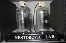
Thought you might like to see a balanced dual 6KD6 mono amp from Mila Nestorovic. 5 E88CCs with a cathode follower 6CG7/6FQ7 driver. I never got a schematic for it.
Other than the sound, I liked the fact that I could use either matched pairs of GE or pre ECG-Sylvania 6KD6s. No need to start trying ones made in the UK or EU etc.
I never tried 6KD6s from Japan, Mila advised to stay away from ones made in Japan and stick with Slyvania 6KD6s. I think he had a bias for Sylvania 6FQ7 and 6KD6 because he used to work for them?
Best from Tucson
Bob
Attachments
Afternoon George, I ordered the "red" board. Woud you make any changes to the component values or any changes at all to drive the "DQ5's"?
Ray
Ray
That is a tough call. I have found that a triode or triode wired pentode in SE mode almost always shows lower distortion at a higher load impedance. This is usually the case in a class A triode P-P amp too. It however is not always the case in a P-P pentode amp running in AB1 or AB2. To add to the uncertainty a class AB pentode amp usually requires some NFB to keep the output impedance under control.
In my experiments with the red board I have seen cases where the distortion is not monotonic. The distortion should increase with increasing power. I have seen it goup, then dip, then go up some more. This is one of those things about the red board that I don't fully understand yet, but it seems to happen more often at higher load impedances. Of course the results will be different with a different driver circuit.
I think that 3.3% at 100 watts is not a problem. Unless you want to thump the walls with disco or rap music your amp will spend very little time in the 20 to 100 watt power range. You want to optimize the distortion in the 1 watt range, and minimize it from 1 to about 20 watts, and don't sweat the higher power stuff. Unless you have big speakers the distortion produced by the speaker as the cone attempts to leave this galaxy will overshadow the amp.
Woud you make any changes to the component values or any changes at all to drive the "DQ5's"?
When I built my red board I made several small component value changes. These were not based on highly technical thinking. They were based on:
1) I desired to build the board without spending any money. All parts were from my junk box.
2) I did not place any of the voltage regulator components since I am using external power supplies. The electrolytics across some of the power supplies were omitted and high voltage film caps were added across the main B+ supply.
3) I knew that I would be cranking the voltage far beyond Petes orininal intention so a few resistor values were increased in resistance and wattage.
4) I increased the B+ voltage a lot further than I originally intended leading to a rather violent parts explosion. Further investigation revealed that the input tubes were operating over their plate voltage spec. I increased some resistor values again to allow operation to 650 volts.
I am preparing for a 2500 mile trip on Monday so I may or may not have time to see exactly what is in my board before I leave. I will get to it If I have time.
George,
Have a safe trip!
Ray
Have a safe trip!
Ray
When I built my red board I made several small component value changes. These were not based on highly technical thinking. They were based on:
1) I desired to build the board without spending any money. All parts were from my junk box.
2) I did not place any of the voltage regulator components since I am using external power supplies. The electrolytics across some of the power supplies were omitted and high voltage film caps were added across the main B+ supply.
3) I knew that I would be cranking the voltage far beyond Petes orininal intention so a few resistor values were increased in resistance and wattage.
4) I increased the B+ voltage a lot further than I originally intended leading to a rather violent parts explosion. Further investigation revealed that the input tubes were operating over their plate voltage spec. I increased some resistor values again to allow operation to 650 volts.
I am preparing for a 2500 mile trip on Monday so I may or may not have time to see exactly what is in my board before I leave. I will get to it If I have time.
Today was day 1 of a 2500 mile road trip. I left Ft. Lauderdale at 5:30 AM and am now typing this in a hotel room in South Carolina at 9:45 PM. I made 3 stops in the Orlando area to buy and sell "stuff". Stop #2 was at the ESRC warehouse where I picked up over $200 worth of tubes and sockets. Stan now has more 6HJ5's in stock (we cleaned him out before). Of course I got 20 more. He now has 12 pin PC board mount sockets. I have not checked to see if they fit the red board, since the sockets are here and the board is 700 miles away. At least 2 of us have cranked plenty of power out of the red board with 6HJ5's.
Stop #3 netted me a few tube type transformers and a "dead" Park guitar amp head. Park was one of the brands Jim Marshall used to sell amps under to get around the restrictive distribution contract he was in from 1965 to 1980.
Stop #3 netted me a few tube type transformers and a "dead" Park guitar amp head. Park was one of the brands Jim Marshall used to sell amps under to get around the restrictive distribution contract he was in from 1965 to 1980.
I tried out 6BH6's in place of 6CB6's the other day. Not bad. I didn't notice any dramatic difference in the sound, but I was using rather bass anemic speakers.
I got a pair of Edcor CXPP 7.6k primary output transformers to replace the toroidals. Nice.
I got a pair of Edcor CXPP 7.6k primary output transformers to replace the toroidals. Nice.
Just wondering if anyone has tried any 6bg6ga's in the amp?
The 6BG6GA like the 807 is a derivative of the 6L6GA. These tubes need at least 250 volts on the screen grid to really come alive. In this amp the screens of the output tubes are tied to the screens of the input tubes. 250 volts on the screen of a 6CB6 will not make it very happy unless the plate voltage is in the same range. While it would be possible to rig up seperate screen supplies for these tubes I don't know if anyone has done this yet. It has been discussed before.
This amp was designed to work with sweep tubes that work with 150 volts on the screen. I do most of the experiments on my board using adjustable power supplies. I have tried at least 20 different output tubes and with one exception the screen supply stayed on 150 volts. The 6JB5's needed 250 volts on the screen so I just cranked the screen supply up to 250 volts and nothing bad happened, so it might work.
SStan now has more 6HJ5's in stock (we cleaned him out before).
Thanks for the tip. The price hasn't changed, so I picked up some more. I have 24 of them now. Nothing like your stash, but it should be enough for me. 🙂 The red board has been in a box for a while now anyway while other, more neglected projects find their way on and off the bench.
The red board has been in a box for a while now anyway while other, more neglected projects find their way on and off the bench.
Mine sits on top of the computer calling out my name and complaining about neglect. Too bad I haven't been home to hear it. I wired some E130L's into it about a month ago, but haven't flipped the switch yet.
My bench is currently occupied by two Simple P-P's, but they have been neglected too. I read a thread about someone who sells amps that run EL84's on 700 volts! I thought I was nuts for cranking them to 450 volts, so there is only one thing left to do. A post in another thread reminded me that I have a big bag full of 8BQ5's somewhere. I think a few of them are going to meet their maker!
Thanks for the tip. The price hasn't changed, so I picked up some more.
I think I have 40 of them. I was thinking of making a monster with 6 or 8 per channel, until I got the 35LR6's. 4 of them should make 400 to 500 watts in a red board like design. I got 50 of them NOS at the Dayton hamfest, but so far 2 out of about 10 are dead. 4 of them make 250 WPC or 504 watts mono blocked in the red board.
Last edited:
George,
What was the transformer impedance for the 35LR6's?
Thanks,
Ray
What was the transformer impedance for the 35LR6's?
Thanks,
Ray
Mine sits on top of the computer calling out my name and complaining about neglect. Too bad I haven't been home to hear it. I wired some E130L's into it about a month ago, but haven't flipped the switch yet.
My bench is currently occupied by two Simple P-P's, but they have been neglected too. I read a thread about someone who sells amps that run EL84's on 700 volts! I thought I was nuts for cranking them to 450 volts, so there is only one thing left to do. A post in another thread reminded me that I have a big bag full of 8BQ5's somewhere. I think a few of them are going to meet their maker!
I think I have 40 of them. I was thinking of making a monster with 6 or 8 per channel, until I got the 35LR6's. 4 of them should make 400 to 500 watts in a red board like design. I got 50 of them NOS at the Dayton hamfest, but so far 2 out of about 10 are dead. 4 of them make 250 WPC or 504 watts mono blocked in the red board.
- Home
- Amplifiers
- Tubes / Valves
- Posted new P-P power amp design