You can't hook the screens up to the UL taps because of the screen voltage limitation of most sweep tubes.....I don't think you could take a sweep tube and get the same amount of linearity using UL than you can with plate-to-grid feedback. Sweep tubes were never intended for audio.
Trust me I have blown enough tubes to realize that sweep tubes must run in pentode mode. Triode and UL are out with a very few exceptions like the 6AV5. Even those will make more power in pentode mode. The red board is capable of 1% distortion at 100 WPC output, I have seen it happen.
Well I just received a bunch of 6HJ5s.
I ran those at 100 WPC for a while with no issues, but I think that I will settle at 60 to 80 WPC in my final design.
I received a box of transformers for free a little while ago so
My collection of "free" transformers had grown to at least 1000 pounds probably a lot more. I went through the ones in my house yesterday and gave about 300 pounds to the scrap metal guy. As Bono would sing "still haven't found what i'm looking for". Of course that is hard to do when you don't know what it is yet.
So, would there be any advantage to a design that does use the UL taps?
Probably not if sweep tubes are the chosen output tubes. If you were using KT88's or other audio pentodes, UL might be worth considering. If you have compatible sweep tubes, the red board is hard to beat.
Pardon all the questions, but I'm still far short of having Morgan Jones committed to memory...
Hey, I have been at this for a long time, and the book of Morgan along with the RC-30 stay on my workbench. I don't even put them away anymore.
Hey, I have been at this for a long time, and the book of Morgan along with the RC-30 stay on my workbench. I don't even put them away anymore.
Ditto on the MJ. I need to get the 3rd edition, though it is kind of pricey for both books. There's no point in committing it to memory as long as you remember that you read it somewhere. 🙂
Thanks to Russ and George for the UL explanations. Please understand I was not trying to "second guess" Pete's design (me?....hardly!). It's just that I'm still learning about the various vacuum tube circuit topologies. Can't wait to hear the red board sing!
Has anyone tried this circuit with non sweep tubes? I have several of the Sylvania super 6BG6GA's. It has been stated that these are NOT high perveance sweep tubes but rather 6L6GC or 7027 with a top plate cap.
Any thoughts on using these tubes or any of the 6L6GC, EL34, KT88 or the ilk?
Any thoughts on using these tubes or any of the 6L6GC, EL34, KT88 or the ilk?
As far as the general topology, I don't see why it wouldn't work. Obviously you'd want more plate voltage for the bigger tubes and definitely more screen voltage for all of them. The input/driver section of this board seems to be able to drive anything I've plugged into it, though I haven't explored what the limits are in terms of voltage swing.
Has anyone tried this circuit with non sweep tubes? I have several of the Sylvania super 6BG6GA's. It has been stated that these are NOT high perveance sweep tubes but rather 6L6GC or 7027 with a top plate cap.
Any thoughts on using these tubes or any of the 6L6GC, EL34, KT88 or the ilk?
hey-Hey!!!,
Those are fine 6L6GC tubes. No reason at all not to use them in this amp topology and I don't see any reason to change anything but the delivered grid bias( Pete's amp is fixed bias?; should get away with a twist of the bias pot).
cheers,
Douglas
Has anyone tried this circuit with non sweep tubes?
A minor circuit modification will be needed to run 6L6 type tubes in this design. First there are the obvious PC board issues since you want to put an octal tube where a 12 pin socket resides. Some creative rewiring could be used here.
The second issue is the screen voltage supply. Pete runs the screens of the input tubes and the output tubes off of the same 150 volt supply. The typical octal audio tubes need more than 150 volts on their screens, usually 300 to 400 volts. The 6CB6 will not be happy with 300 volts on the screen and 140 volts or so on the plate. It should be possible to lift some resistors and run some flying wires to run the output tubes on a supply derived from the plate voltage source.
Well I was trying to find a transformer for the bias supply and for whatever reason the transformer that would have worked I had didn't like me too much and let out the magic smoke. So I am still searching. Antek has a 50va dual 25v secondary transformer that I thought might work if I put the windings in series to get 50vac. Any opinions on that.
Last edited:
That will work fine...overkill in terms of VA but the magic smoke should have a better chance of staying inside.
hey-Hey!!!,
For bias and CCS negative rail service I like the $7, 25.2V/450 mA trans from Radio Shack. I use either a doubler or a FWB depending on the use; the half-rail voltage usually gets the CCS attached and full doubled voltage goes to bias. How that'd work on Pete's board is a bit of an open question.
cheers,
Douglas
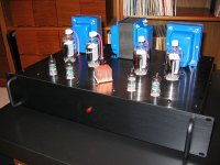
The "Red Board" sings!
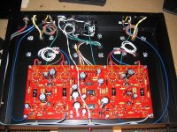
With the arrival (at last) of the Edcor iron yesterday, I finished Pete Millett's "Engineers Amplifier" (aka DCPP) this afternoon. This has been one of my most satisfying tube projects to date; mostly due to Pete's excellent PCB and error-free BOM and instructions.
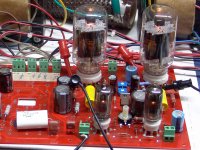
I built my DCPP pretty much as per Pete's original, deviating only on the chassis type and use of 6JM6 (plate cap) Compactrons. The PCB is beautifully laid out, and stuffing it is a breeze. The PCB is worth every cent Pete asks for it.
I can't comment on the design as the details of it are way beyond my knowledge. However, I do have a good set of ears and some very good audio gear as a reference. I built this amplifier confident in knowing Pete's reputation in the DIY community. I wasn't about to be disappointed.....
I connected some cheap speakers and a CDP, and threw the switch for the first time. Tubes lit and music played! I connected some DVM's to the handy test points on the board, and set the bias and driver balance. Easy.
After about an hour, the circuit stabilized nicely with 40ma on the Compactrons. And yeah... no hum, no hiss. This baby is background quiet!
At first, I thought of connecting the DCPP to the bookshelf speakers I usually use with a "small" amp. But what the hell...instead, I hooked up my Vandersteen 2ce Signatures. The 87db Vandys usually laugh at little amplifiers, only playing well around 70wpc and beyond.
Popping a familiar Wayne Shorter CD in the player, I sat down fully prepared to be under-whelmed. Not! The DCPP made me sit up and take notice....this thing kicks ***!! Talk about dynamics. The Millett design does deep, tuneful bass along with clear and sparkling highs. Other discs showed more good stuff. Overall, it's a very honest and revealing amplifier. In a nutshell, I'd say the best qualities of tubes, with the punch of solid-state.
I imagine with 50-100 hrs on the circuit, the sound will be very near equipment costing much, much more. It's going to be fun playing music with the DCPP.
Many thanks to Pete Millett for the design and the quality PCB. And thanks too, Pete, for your other, generous contributions to the DIY audio community.
With the arrival (at last) of the Edcor iron yesterday, I finished Pete Millett's "Engineers Amplifier" (aka DCPP) this afternoon. This has been one of my most satisfying tube projects to date; mostly due to Pete's excellent PCB and error-free BOM and instructions.
I built my DCPP pretty much as per Pete's original, deviating only on the chassis type and use of 6JM6 (plate cap) Compactrons. The PCB is beautifully laid out, and stuffing it is a breeze. The PCB is worth every cent Pete asks for it.
I can't comment on the design as the details of it are way beyond my knowledge. However, I do have a good set of ears and some very good audio gear as a reference. I built this amplifier confident in knowing Pete's reputation in the DIY community. I wasn't about to be disappointed.....
I connected some cheap speakers and a CDP, and threw the switch for the first time. Tubes lit and music played! I connected some DVM's to the handy test points on the board, and set the bias and driver balance. Easy.
After about an hour, the circuit stabilized nicely with 40ma on the Compactrons. And yeah... no hum, no hiss. This baby is background quiet!
At first, I thought of connecting the DCPP to the bookshelf speakers I usually use with a "small" amp. But what the hell...instead, I hooked up my Vandersteen 2ce Signatures. The 87db Vandys usually laugh at little amplifiers, only playing well around 70wpc and beyond.
Popping a familiar Wayne Shorter CD in the player, I sat down fully prepared to be under-whelmed. Not! The DCPP made me sit up and take notice....this thing kicks ***!! Talk about dynamics. The Millett design does deep, tuneful bass along with clear and sparkling highs. Other discs showed more good stuff. Overall, it's a very honest and revealing amplifier. In a nutshell, I'd say the best qualities of tubes, with the punch of solid-state.
I imagine with 50-100 hrs on the circuit, the sound will be very near equipment costing much, much more. It's going to be fun playing music with the DCPP.
Many thanks to Pete Millett for the design and the quality PCB. And thanks too, Pete, for your other, generous contributions to the DIY audio community.
Attachments
Last edited:

Need some help
Hi all,
I am having trouble finding the correct 7 pin sockets for this project. I have order 2 set from 2 different places and I so far none of them fit in the board. Anyone out there willing to share their source and part number with me?
Cheers,
Alan
Hi all,
I am having trouble finding the correct 7 pin sockets for this project. I have order 2 set from 2 different places and I so far none of them fit in the board. Anyone out there willing to share their source and part number with me?
Cheers,
Alan
Hi all,
I am having trouble finding the correct 7 pin sockets for this project. I have order 2 set from 2 different places and I so far none of them fit in the board. Anyone out there willing to share their source and part number with me?
Cheers,
Alan
Hey Alan...
I got mine from the tubestore.com
7 Pin Socket for Miniature Tubes
You do have to tweak (bend outward) the tabs a bit to fit the board. It's not a problem.
Last edited:
Hey Alan...
I got mine from the tubestore.com
Those look like the same ones that I used. I am sure that they all come from the same Chinese source. Verify that the tube actually fits in the socket before soldering it into the board. I have found more than one of the 9 pin versions of this socket with one or two holes that were too small.
Those look like the same ones that I used. I am sure that they all come from the same Chinese source. Verify that the tube actually fits in the socket before soldering it into the board. I have found more than one of the 9 pin versions of this socket with one or two holes that were too small.
George...
You make a very good point that did, in fact, come up during my build.
I'm sure all current ceramic sockets of this type do indeed come from China. Good thing too, as we'd have a tough time finding the odd-ball sockets for Compactrons etc.
Anyway, I found these sockets have very tight fitting retainers. If I would have forced the issue, I would have ended up with broken glass in my hand! You need to take a very finely-pointed object (I use a dental pick) and open up the metal retainers just enough for a good fit. I had to do this on every 12-pin and 7-pin socket I bought. As a matter of fact, if you looked at the sockets, as purchased, you could see some of the retainers were fully closed up!
I got mine off of eBay from a vendor that turned out to be ESRC. Same deal...the legs had to be bent outward. This might be on purpose (Pete?) because when you do this the height of the 7 pin sockets matches the 12 pin sockets very well. Otherwise they are a bit taller.
I got mine off of eBay from a vendor that turned out to be ESRC.
I got mine at a hamfest, but when I buy sockets at most hamfests I get them from Stan (ESRC) unless I am looking for something that he doesn't have.
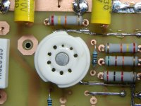
These sockets are of the two piece variety. There is a ceramic cover that holds the pins in the socket. I have found a few cases where the holes in the top ceramic cover are smaller than the tube pins. Enclosed is a picture of the very first Simple P-P prototype board. I built the entire board and then found out that one of the 12AT7's doesn't fit. I then tried to drill the ceramic with a Deremel tool resulting in a drill bit broken off in the hole. I no longer use the 2 piece 9 pin sockets, but I haven't seen a one piece 7 pin socket yet.
Attachments
Mmm...never had any Chinese sockets from tubestore.com or Pacific TV, (my other socket supplier) with small holes like that example. I would guess both those dealers check 'em first for the obvious defects.
Just wondering if someone could help me with some questions. I'm thinking of converting a 6L6 PP amp to the DCPP circuit. It has the usual four 8-pin sockets and four 9-pin sockets in the top plate and is wired point to point. The DCPP PCB is too wide to fit in the 12" (300mm) chassis so it would have to be wired point to point. I discovered by chance that a 6FW5 tube will fit the 8-pin sockets and the specs/datasheet are very close to the 6JN6 except the gm is 6600 vs 7300, and approx plate resistance is 20K vs 18K. Max ratings are identical on the GE datasheets. Would this be close enough or am I better off fitting new sockets and using the specified tubes? Does anyone know of an equivalent 9-pin tube to replace the 7-pin 6CB6 sharp cut-off pentode?
The rest of the hardware should be suitable, the power tranny has an independent bias winding, B+ is around 360V, the heater windings can support EL34 so they should be OK, the OPT's primary impedance should be in the ballpark, and there is room to fit a PCB for the screen regulator/bias supply/B+ ripple filter. I've been looking for an interesting cct to put into this amp for a while, and this might just be the ticket?
The rest of the hardware should be suitable, the power tranny has an independent bias winding, B+ is around 360V, the heater windings can support EL34 so they should be OK, the OPT's primary impedance should be in the ballpark, and there is room to fit a PCB for the screen regulator/bias supply/B+ ripple filter. I've been looking for an interesting cct to put into this amp for a while, and this might just be the ticket?
- Home
- Amplifiers
- Tubes / Valves
- Posted new P-P power amp design