Got about 30WPC out of the 6HJ5 at 350V B+, but I was having some trouble with runaway at higher voltages. I'm only using pin 11 to control the grids.
I looked at my board and I only have pin 11 connected.
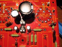
I'm also thinking that 1k is too high for a screen resistor
Usually a bigger screen resistor helps in the runaway department, but I have 620 ohms on my board. That resistor value was based on the fact that it was the first reasonable value that I found when digging for parts during the build. My grid stoppers are 1K 1/4 carbon comp (again based on availability). The other deviation from the normal build is that I am using a regulated power supply for my negative voltage and I have it set on 75 volts. Some big sweep tubes need even more.
I have run my 6HJ5's to 600 volts briefly but settled on a lower voltage until I swap out a few capacitors to prevent another explosion. I am using the 3300 ohm connection of those OPT's to get more power.
Thanks. One of my tubes appears to have an internal short. I tried it one more time and I saw a little yellow spark inside before it went nuts. Reset back to 350V and I could make the bias go wild by tapping on the tube.
I'm also using a regulated supply for the bias, but it is connected at one of the rectifier diodes so simulate the real conditions more. I'll play with it again today if I have time.
I'm also using a regulated supply for the bias, but it is connected at one of the rectifier diodes so simulate the real conditions more. I'll play with it again today if I have time.
Swapped the two tubes that were giving problems. The amp is more stable now. The last batch of 6HJ5s Stan sent me were not well packed...they were sort of flopping around in the box.
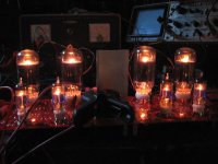
Got 80WPC at 500V B+ until the fuse blew on the variac, LOL. I keep a small fuse in there...probably 2A or something. This is through the mystery transformers. They are 60s vintage, so if I assume they are 8 and 16 ohm taps then I measured about a 6.4k primary. Based on the weight they are probably 50W iron, so I am probably reaching the limits of what I can do. This was with an 8 ohm load on the 16 ohm taps.
Got 80WPC at 500V B+ until the fuse blew on the variac, LOL. I keep a small fuse in there...probably 2A or something. This is through the mystery transformers. They are 60s vintage, so if I assume they are 8 and 16 ohm taps then I measured about a 6.4k primary. Based on the weight they are probably 50W iron, so I am probably reaching the limits of what I can do. This was with an 8 ohm load on the 16 ohm taps.
This is through the mystery transformers.....They are 60s vintage
Are you referring to the transformers that you got from me? That's what I see in your picture. If so the date code on the carton that I took that pair from reads 9016, early 1990. They are 6600 ohms CT with 4, 8 and 16 ohm taps. Black is common with yellow being the 4 ohm tap, green-yellow the 8 ohm tap, and green being 16 ohms. I was using the black and green wires with an 8 ohm load for my 6HJ5 experiments. This will reflect a 3300 ohm load to the tubes. The spec sheet said that these were 80 VA transformers intended for use in a guitar amp from 80 Hz to 4 KHz. The actual useful power rating is limited by saturation and depends on what frequency range you want. From 20Hz to 20KHz you can put about 15 watts through these transformers before they begin to distort. From 30 Hz up 25 to 30 watts is OK. At 1KHz I have run almost 200 watts through one without distortion or smoke. At this frequency I am afraid of insulation breakdown due to voltage at any higher power.
I had the 6HJ5 amp set up for 100 WPC and it sounded very nice through my Yamaha NS10M speakers with no audible distortion on bass notes that threatened to shred the speaker cones. These speakers have no response below 70 Hz.
One of my tubes appears to have an internal short. I tried it one more time and I saw a little yellow spark inside before it went nuts.
I had one that put its own internal light show before sparking out. Lots of purple lightning bolts inside it. That resulted in me testing all 20 but it was the only bad one. I got 20 more last weekend, but have not had time to test them yet. Stan replaced the bad one from the last batch.
Sorry George, I'm referring to a set of OPTs I have that I mentioned earlier. I did some more tests and they are pretty flat down to about 30Hz at 60WPC.
I hooked up some tunes, but got very low and distorted output. Back on the signal gen it sounds and looks fine. Something has gone awry after the recent torture tests, because it sounded fine when I had the 6JN6s in there. Need to check the CCS and input section.
After a minute or two at 500V and full output, I'd start to notice a smell. Apparently R21 doesn't like dissipating 9W.
Attachments

So...if I had a 100 watt transformer with a 1900 ohm primary and a 4 ohm secondary, if I put an 8 ohm load on the secondary, I should have a 3800 ohm primary. My question is, is there anything wrong with doing that if I needed a 3800 ohm primary?
Thanks,
Ray
Thanks,
Ray
In theory it will work. In practice it will work, but.... There are several important specs required for an OPT. The important spec here is primary inductance. Less inductance is required for a 1900 ohm OPT than a 3800 ohm OPT. This means that your transformer will reflect a 3800 ohm load to the tubes. It may not have enough inductance for 100 watt operation at its low frequency spec. If the transformer was rated for 100 watts at 20 Hz, you may not get this. Maybe you will get 50 or 60 watts at 20 Hz (or whatever the original spec was) and full power may not be available until maybe 50Hz or so. It is also possible that you will get full power at the lowest frequency too. The only way to find out is to try it.
Since you are asking this here I am assuming that this is a P-P OPT. I have had better luck doing this with P-P OPT's than with SE OPT's. I have a 1250 ohm OPT that I have been using with this board at 2500 and 5000 ohms, with excellent results. It is however rated for 400 watts so I haven't tested the limit yet!
Since you are asking this here I am assuming that this is a P-P OPT. I have had better luck doing this with P-P OPT's than with SE OPT's. I have a 1250 ohm OPT that I have been using with this board at 2500 and 5000 ohms, with excellent results. It is however rated for 400 watts so I haven't tested the limit yet!
Getting tired, so I unplugged it for the day. Not quite sure what the trouble is. Still having some runaway issues, just randomly sometimes. Next step will be to go back to George's OPTs. Starting to wonder if these have moisture damage. They spent a few decades in my parent's garage loft.
Kind of a pain working on this board since all the components are on the bottom. Thought about building it with the components on the other side, but I have intentions of using the board in an amp eventually.
Kind of a pain working on this board since all the components are on the bottom. Thought about building it with the components on the other side, but I have intentions of using the board in an amp eventually.
Russ I was curious what kind of B+ you were getting with that antek transformer running on 120vac. I assume the 500v was due to you cranking your variac up a bit?
It came right in at 450V under load. Note that I startup the amp with the variac turned down because at that level the unloaded voltage is too high (well over 500V). The plan is to either modify the ripple filter circuit slightly and add a zener string so that it acts as more like 500V regulator when not under load or to find some other way to soft-start B+.
I figured it would need a bit more work then just tossing a couple of inrush current limiters on the hot line coming in and one on the HV center tap. I think I bought 500v capacitors. I will have to take another look. I know I couldnt source 500v 10uf radial caps.
I thought I was going insane yesterday. Turns out that one of these mystery transformers is phased opposite of the other. Normally this wouldn't matter that much, but since I had both OPT "commons" grounded and my shop speakers have their negative wires tied together at a switch box, it ended up mostly-shorting one of the channels...but only when both OPTs were connected. Couple that with the really strange experience of seeing a fair amount of output coming from an amp with no output tubes in it, it makes one question their sanity. The latter behavior is due to the driver stage feeding the OPTs backwards through the plate-to-grid feedback resistors. I wouldn't expect to see much output through a pair of 220k resistors, but boy was I wrong.
After I finally figured it out...I went to bed just in case I really was off my rocker.
After I finally figured it out...I went to bed just in case I really was off my rocker.
I thought I was going insane yesterday.
You'll have to do a better job of demonstrating sanity...maybe the strawberries were in the wardroom locker 🙂
Saw your site -- I have a Hemi Magnum -- first car in 20 years which has had zero problems -- (the prior mo prob car was a 225) -- traded in a MB500E Wagon for the Dodge and never looked back.
You'll have to do a better job of demonstrating sanity...maybe the strawberries were in the wardroom locker 🙂
Maybe the messboys did eat them.
Saw your site -- I have a Hemi Magnum -- first car in 20 years which has had zero problems -- (the prior mo prob car was a 225) -- traded in a MB500E Wagon for the Dodge and never looked back.
Glad to hear that! I have a lot of friends with Rams and Dakotas and they seem to be very reliable. Me...I'm still stuck in the 80s.
Returning to the world of the sane. Everything works fine now with everything hooked up and powered sanely. The heaters on these tubes max-out the 6.3V windings on the transformer, so it turns out that the voltage surge at powerup is only about 460V. No need for special power-on mods with the AN-4T360 and 6HJ5s. The surge was worse with the 6JN6s as their heater requirements are much lower. In fact, B+ sags to around 420V with the tubes biased at about 50mA. The tubes want more volts and more current. Time to pull-out the AN-4T400.
George, what are you idling these tube at? I went as high as 80mA and they seemed to want it and more, but I don't think I can sustain such high currents on both channels with the on-board power supply.
Listened to it for an hour or so at normal settings (420VB+, 50mA bias) playing some really heavy bass stuff (ASoT). This thing kicks the stiff woofers on my shop speakers with even more authority now! My wife was not pleased that the living room upstairs was rattling, but I've never heard these speakers sound this good (Boston Acoustics A60s).
On the dummy load I got about 60WPC at clip at this B+ level. If I crank the variac to the max I get about 80WPC. The tubes showed no sign of distress and the amp was very stable. The only problem with increasing the headroom is the amp needs more gain to use it. A preamp would be a must to reach its full potential, but how much power do I really need?
Attachments

Last edited:
George, what are you idling these tube at? I went as high as 80mA and they seemed to want it and more, but I don't think I can sustain such high currents on both channels with the on-board power supply.
I tried several different current settings with several different tubes and came to the conclusion that Pete was right with 40 mA. Except for the reall small tubes 40 mA seems to be the knee in the power VS distortion VS glowing tubes curves. The difference in power from 40 mA to 60 mA was less than a watt. Distortion has leveled off by 40 mA too. I didn't notice much change in the sound with higher current either. I may change my mind upon further analysis, and your results may vary with different speakers.
The old guys that used to build tube type ham radio transmitters told me that for a given dissipation the tubes will live longer at a higher voltage and lower current, because the cathode doesn't need to spit out as many electrons. Don't know how true that is, but I find that more voltage makes more power with sweep tubes.
Time to pull-out the AN-4T400.
I have a 4T360 and two 4TK400's. I started swapping out caps with the idea of trying the 4TK400. The 4TK400 made over 500 volts in my Simple SE.
It made a little more power at higher currents with no noticeable change in the distortion numbers. This is all without GNFB. Sound-wise, the bass got tighter. I'm wondering if a lower primary impedance is needed to take advantage of more current.
Got one of those, too.
I have a 4T360 and two 4TK400's. I started swapping out caps with the idea of trying the 4TK400. The 4TK400 made over 500 volts in my Simple SE.
Got one of those, too.
Last edited:
I think I know the transformers you were considering. I could be wrong but I was also wondering if this would work well or not with the antek AT-100L transformers. They have the following specs:So...if I had a 100 watt transformer with a 1900 ohm primary and a 4 ohm secondary, if I put an 8 ohm load on the secondary, I should have a 3800 ohm primary. My question is, is there anything wrong with doing that if I needed a 3800 ohm primary?
Thanks,
Ray
SPECIFICATION:
Output power 100 Watt
Turn Ratio 15.5:1
Ultra Linear tap 40%
Primary impedance 1922 ohm
Primary DC resistance 85 ohm
Output impedance 4 & 8 ohm
Output DC resistance 0.2 & 0.2 ohm
Frequency response 10 – 50000H
Although a pair of 100watt Edcor's run only $4 more than these each. I recently picked up another batch of tubes from the guy who gave me that last one and I am hoping there will be something suitable to this amp in there. I have to do some sorting.
My plan was to run the amplifier with the power transformer Russ is using. I could probably get away with using one of the other antek output transformers as it seems I am only going to be outputting around 60watts if I were to choose the 6hj5 tubes. Antek has a 70 watt transformer with no UL tap that has a 2900ohm input impedance which might make a decent output transformer for one of these.
Last edited:
Yes, I was also looking at Antek's OPTs recently. The AT-070L seems like it would be a suitable match for the setup as I have it right now. Their OPTs are a little unproven...I can't find anyone on the board that has bought them and reported results. For that price it is almost worth getting a pair anyway and putting them to the test. George is probably better candidate for doing that than me.
- Home
- Amplifiers
- Tubes / Valves
- Posted new P-P power amp design