I looked at the power supply at lunch time. It is an HP 6448B, 0-600V 1.5A SCR regulated supply. Two handle carry, but I can lift it.
I might leave work early and see if they will come down on price. $100 is a good deal on it, but I really don't have room for another boat anchor.
I might leave work early and see if they will come down on price. $100 is a good deal on it, but I really don't have room for another boat anchor.
It is an HP 6448B, 0-600V 1.5A SCR regulated supply. Two handle carry, but I can lift it.
That is exactly the same power supply I am using to run the red board and perform all of my "over 100 watt" experiments. It can be seen in posts #222, 218, 232, 233 and many more I'm sure. I couldn't remember the number so I looked at the pictures in those posts. It will go to 650 volts and 1.7 amps if turned all the way up, and the previous warnings about blowing stuff up apply. The fan is definitely loud, but mine may be abnormal, it was wet. I still use the "small" power supplies for "small" amps, but this guy is the "go to" power supply for just about anything bigger than a Simple P-P or Simple SE. In fact many of my previous experiments (screen drive, cathode follower) ended because I didn't have enough power supply to find the limit of the design. Now I am limited by the wall outlet. Cranking this power supply full up will blow the bench breaker!
I might leave work early and see if they will come down on price. $100 is a good deal on it.
If you think about it, I drove to Orlando (400 mile round trip) so I spent at least $50 in gas, lots more if I took the truck (don't remember), and offered my time for most of the day (it was fun) while the women went to the mall. I never saw the credit card bills, so $100 is probably cheaper than mine!
A really heavy box arrived today with 3 Anteks in it. I ordered 6 total. one was the AN-4T360. Time for the Simple PP to vacate the bench.
Also finally completed Pete's sound card interface. Still waiting for a Audiophile 192 to come (backorder). It works "OK" with an SB Live, but the analog section seems to be fairly noisy.
Also finally completed Pete's sound card interface. Still waiting for a Audiophile 192 to come (backorder). It works "OK" with an SB Live, but the analog section seems to be fairly noisy.
Let us know how the experiments go Russ. 6 transformers....what was that a 60lb box? Your mailman must have loved you.
George (and any one else with an SCR controlled HV PS),
How sensitive are these power supplies to lead length?
If I get the PS, I will need to run at least 8' leads from it to the work bench.
I know some power supplies without sense leads are very sensitive to lead length.
Any precautions on loading such as adding a pi filter at the UUT recommended, or not recommended?
George (and any one else with an SCR controlled HV PS), How sensitive are these power supplies to lead length?
The HP unit in question has a rather large cap in parallel with the output terminals already (inside the power supply). I have about 4 feet of wire connecting it to the red board (or any other experiment). I have not needed to provide any other filtering at the unit under test (UUT) with this supply. I usually include some type of bypass at the amp on most of my test amps just as a general precaution against "funny stuff". The red board is no exception. There is a flat white cap wired from B+ to ground in the area where the voltage regulator fets should go. It is a 1.5uF 600V ASC cap of unspecified quality that I got by the handful at a hamfest. The next time I experiment with this board I plan to replace it and some of the electrolytics with higher voltage caps since I have blown one cap in half already. That experience has kept my use of the voltage knob to about 550 volts, but "this one goes to 11".
My other supplies, especially the Fluke 407D, require a motor run or other large cap right at the unit under test to avoid provoking motorboating or oscillation when the current meter gets pegged. All of my power supplies are low cost bargain units still running their 50 year old caps and I tend to ask too much of them. I have not had to do anything special with the HP, but then I have not yet tried to run it at 11 yet!
I did use it to blow up some gassy 6V6's that needed to die, and it made all sorts of funny noises, and blew the bench breaker twice, so I guess that qualifies as 11. No problems with the supply though.
Just go and buy it Steve, and stop teasing us. You will not regret 🙂 Give him $110 if you have to...I'll send you ten...
George (and any one else with an SCR controlled HV PS),
How sensitive are these power supplies to lead length?
If I get the PS, I will need to run at least 8' leads from it to the work bench.
I know some power supplies without sense leads are very sensitive to lead length.
The nH per inch is not as relevant as the gbw of the error amplifier in the power supply -- long power supply leads are a receiving antenna - a little unexpected energy on the leads and you can send a power supply into oscillation. It's a bigger issue with ss power supplies in which the error amplifier is run with little or no compensation.
I use Pomona cables from my HV supply (a Heath IP-17) and have no problems.
For measurement of really low-noise equipment I use CAT5 cable and connect all the striped wires together at the measurement instrument.
I use Pomona cables from my HV supply (a Heath IP-17) and have no problems.
I shouldn't say what I use on my power supply since it came from Walmart, and carries no voltage rating. To avoid pick up issues the two wires are lightly twisted and ty-rap'ed together. The bandwidth of the control loop in this supply is probably measured in Hz, and not very many of them.
For measurement of really low-noise equipment I use CAT5 cable and connect all the striped wires together at the measurement instrument.
Because of the slow control loop in this supply the current limiter takes hundreds of milliseconds to engage. There is a big cap in the output circuit that can store a lot of energy. It will release this energy into an accidental short circuit. After witnessing what this guy did to a 10K 2 watt resistor and a 47uF 450 V cap, I would venture a guess that it could vaporize a pice of CAT5. I may try to "estimate" the SS capability of this supply some day but I already know that it will instantly blow the little link that connects the cathode of a tube up to the pin. Somewhere on this forum there are pictures of a 6AX4 with multiple holes in the plate, and a cool blue death ray shooting through one. Those were done with an 8 ohm 500 watt resistor in series with the supply.
I must also mention another "observation". Many of us use the typical dual banana plugs that mate with the jacks on the front of the supply. You run the wires through holes in the plug and tighten the set screws. The bare ends of the wires protrude through the plug. Trust me a temporary loss of vocabulary control will result if you try to yank the plug quickly when your circuit starts smoking. Cut the stubs short and cover them with hot melt glue!
Last edited:
Thanks for the safety tips, I'll need them. The boat anchor is in the back seat of the truck.
I'll get some of the 1KV rated rubber insulated probe wire to use for wiring it up to the DUT. I'll make sure the banana plugs don't have exposed wires I can grab by mistake or have arc to me.
Has any one got a PDF of the manual they could send me? I've not been able to find one on the web.
I'll get some of the 1KV rated rubber insulated probe wire to use for wiring it up to the DUT. I'll make sure the banana plugs don't have exposed wires I can grab by mistake or have arc to me.
Has any one got a PDF of the manual they could send me? I've not been able to find one on the web.
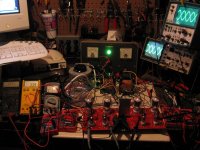
Let there be volts. This is the "stock" setup with 6JN6s. Got about 21W before clipping @ 1kHz. The GNFB loop was not hooked up, but the spectra looked decent even though the tube matching was poor. I didn't spend any time trying to find a better match. Setting the bias was touchy.
The board is powered by the AN-4T360 on a variac to give me 340V B+. Bias is coming from the bench supply right now. Tested it for maybe 5 minutes before hooking up speakers and playing some music. Sounded good and had plenty of power to kick around the "good" shop speakers, which are not easy to drive.
Next step is to reconfig for 6HJ5 and see how the stock PSU filtering behaves at higher B+ voltages and currents. That makeshift heat sink got quite warm during this quick test.
Attachments
Oh, and the 6JN6s cranked to 450V B+ briefly yielded a little over 40WPC at clip.
Yow!
I have heard these sweep tubes are tough, but how long will they last under continuous 450V? Interested to see (and hear) the distortion at 40wpc.
My spidey sense was tingling, so I didn't let it go for more than a minute or so. Low order distortion wasn't pretty as I was into clipping at that point, but the high order wasn't as horrible as I was expecting.
My Audiophile 192 is *finally* shipping, so I can hopefully get better signal sources and analysis. I tried it with my EMU10k (SoundBlaster Live!) and there was a lot of noise being introduced into the signal. These were all done on the Velleman.
My Audiophile 192 is *finally* shipping, so I can hopefully get better signal sources and analysis. I tried it with my EMU10k (SoundBlaster Live!) and there was a lot of noise being introduced into the signal. These were all done on the Velleman.
I have heard these sweep tubes are tough, but how long will they last under continuous 450V?
450 volts is idling for a sweep tube. The max spec for continuous DC plate voltage for a 6JN6 is 770 volts with the maximum positive peak voltage of 6500 volts. A sweep tube in a TV set lives a tough life there is no "volume control" on the sweep circuit. It runs at full power all the time, for several hours at a time.
In post #139 I fired my board up for the first time. I ran the 6JN6's at 450 volts and got about 50 WPC. In post #149 I started turning the power supply up which resulted in more power. 600 volts makes 80 WPC and exploded the 450 volt cap on the B+ line. I noticed no issues with the tubes at 600 volts even though the dissipation was above the spec. In fact I was about to turn it up to 650 when the big bang happened.
Last night I began changing out the capacitors in preparation for a journey to the end of the power supply knob!
Hmmm...you are right. Just checked my math and I was maybe pushing 16W on the plates at idle. I didn't not notice any glow or anything. The OPTs were singing quite loudly, though. 🙂 I was a bit boggled at how much power those little guys can put out.
One thing is for certain, Pete's amp in the stock configuration should be very good tube longevity.
Another funny thing was when I put the wrong type of pentode in one of the sockets for the input/driver stage. I can't remember what kind it was, but it had very large plates and was probably a spare for the Hammarlund. It worked fine next to the 6CB6A! In fact, I didn't even know what I did until I leaned over and noticed the construction of one of the tubes was completely different. Guess I got lucky on the pinout, but it is a testament to the LTP with a real CCS in the tail. 😉
Another funny thing was when I put the wrong type of pentode in one of the sockets for the input/driver stage. I can't remember what kind it was, but it had very large plates and was probably a spare for the Hammarlund. It worked fine next to the 6CB6A! In fact, I didn't even know what I did until I leaned over and noticed the construction of one of the tubes was completely different. Guess I got lucky on the pinout, but it is a testament to the LTP with a real CCS in the tail. 😉
So with the variac cranked to eleven (well, "100", but that's 140VAC) I got just under 500V of B+ while driving both channels just into the rails. Got 60WPC from the 6JN6s.
This is already my most powerful tube amp right now and I just got started, LOL.
This is already my most powerful tube amp right now and I just got started, LOL.
Had a few moments to play with it again. Got about 30WPC out of the 6HJ5 at 350V B+, but I was having some trouble with runaway at higher voltages. I'm only using pin 11 to control the grids. Maybe I should use pin 3 too? I'm also thinking that 1k is too high for a screen resistor.
- Home
- Amplifiers
- Tubes / Valves
- Posted new P-P power amp design