Such linearity seems useful in class A or B. I'm not too sure bout AB crossing...
I suppose no easy way to trace how two curves interact in push-pull?
I suppose no easy way to trace how two curves interact in push-pull?
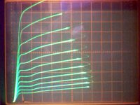
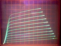
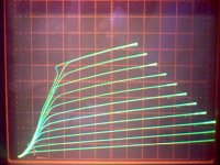
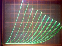
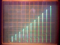
Here are some curves for the 35LR6 in various modes:
Plot1: g1 pentode: 50 V/div horiz., 100 mA/div vert., 125 V on g2, 2.7 V steps on g1
Plot2: g2 pentode: 50 V/div horiz., 50 mA/div vert., 5.3 V steps on g2
Plot3: g2g1 scaled: 20 V/div horiz., 100 mA/div vert., 5.3 V steps on g2, 5.3V/3.5 steps on g1
Plot4: triode config.: 20 V/div horiz., 50 mA/div vert., 5.3 v steps on g1
Plot5: g1 pentode: g1 volt versus plate volt (stepped)
Plot 5 seems to be the only gain function available, and I don't see any ready way to use it for P-P
Re: Kenpeter:
I have another equipment setup that I have yet to try out for measuring gain plots across the signal range. (which would work for P-P stages or diffl stages or even multiple stages) Eventually it will have the capability for stepped parameter multiple graphs of gain (like stepped load resistance or stepped voltage op points) It uses a small 1 KHz signal combined with a ramp to sweep across the signal range, and then uses a 1 KHz filter/detector on the output signal to measure gain versus the ramp voltage. Later on, the ramp completions will be used to control a counter for stepping some parameter via a D/A control.
Attachments
Last edited:
This is very interesting data. I'm sure I can get at least 200V p-p with a pentode input stage without working too hard. 100W out from a single tube into 8 ohms with a 5k transformer requires 400mA peak from the output tube, well within the ratings of the 35LR6 (and lots of other sweep tubes) It only takes 20-25V of drive to get there using the scaled g1-g2 drive, leaving me some gain margin for feedback. Food for thought and grounds for further research...
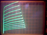
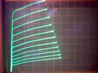
The little runt 6GF5 doesn't seem to have any datasheets either. Here are plots of the 6GF5 and 6GE5 under identical conditions (I didn't even have to touch up the bias, virtually matched), both GE manufactured.
I'd say they are the same tube, 6GF5 is just a chopped 6GE5. Can convert their datasheet gm's for similar currents with GM/gm = (Ip/ip)^.66 Same again.
Plot1: 6GF5: 50 v/div horiz., 20 mA/div vert., 100 V on g2, 1.4 V steps on g1
Plot2: 6GE5: ditto
I'd say they are the same tube, 6GF5 is just a chopped 6GE5. Can convert their datasheet gm's for similar currents with GM/gm = (Ip/ip)^.66 Same again.
Plot1: 6GF5: 50 v/div horiz., 20 mA/div vert., 100 V on g2, 1.4 V steps on g1
Plot2: 6GE5: ditto
Attachments
This is very interesting data. I'm sure I can get at least 200V p-p with a pentode input stage without working too hard. 100W out from a single tube into 8 ohms with a 5k transformer requires 400mA peak from the output tube, well within the ratings of the 35LR6
I cranked the 6LR6's to 180 watts in post #228. Peak cathode current was just under 800 mA (well within specs). This was with a 2500 ohm load on 550 volts. Of course this was G1 driven. My other driver board will mave over 200 V p-p with 6SN7's in LTP. It needs a fair amount of B+ voltage, but if you are thinking about making a big amp with big tubes, plenty of voltage is a requirement.
The little runt 6GF5 doesn't seem to have any datasheets either.
I'll catch the ones that ran and hid under the bench and stuff them in the board, but it won't be for a couple of weeks. No more experiments for a while. I will be away next weekend, but I should return with some more "test subjects". I have some 6GE5's somewhere, but I don't know if I have 4 of them.
I was counting on at least 550-600V for the output plates. Seeing as driving down to 40V plate is relatively easy, this will be enough and then some for 100W output. I chose a 5k output transformer as compromise between treating the tubes with kid gloves to reduce distortion vs. kicking the living snot out of them. I'll probably start out with using the Edcor 5k 100W iron.
I was counting on at least 550-600V for the output plates. Seeing as driving down to 40V plate is relatively easy, this will be enough and then some for 100W output. I chose a 5k output transformer as compromise between treating the tubes with kid gloves to reduce distortion vs. kicking the living snot out of them. I'll probably start out with using the Edcor 5k 100W iron.
That's a good load line for getting 100W out of a pair of 30W sweep tubes (or 6550s or 6146Bs for that matter). 500 volts peak anode swing, 1250 ohms load (5K A-A) and 100W Po. Depending on quiescent current, you dissipate about 28W per anode.
You mentioned screen drive. With a 5K OPT I don't think screen drive is really needed for the current capability, but I am nonetheless intrigued by the idea of combination g1+g2 drive used with plate feedback. The improved linearity down to very low plate currents might make for a low idle current OP and smooth crossover.
If g1=g2/mu drive can reduce the drive voltage needed then it becomes a good candidate for the Schade-ey parallel current feedback topology using a pentode driver + powerdrive buffer(s).
Somewhat related but a little more off-topic, Is there any practical issue with large-ish negative excursions of g2? Other than an unnecessarily negative power supply for class AB? I have been wondering if there is any advantage in clamping the negative excursion of the "off" tube in class AB.
I guess this is going off the threads topic, sorry.
Michael
PS Some 30w+ sweep tubes that would get you into 100W space
6HF5
6JS6
6KN6
6LB6
6LR6
6ME6
6LQ6
6KD6
6KG6
6LF6
Last edited:
Quick dumb question - could noise be introduced if I tie-wrap the feedback loop connection to the line-in connection for cable-management purposes? The line-in wire is shielded (coax) and nice and stiff so I was thinking of using it as a convenient way to route the comparatively floppy feedback loop wire that runs between the (+) output and the NFB connection.
Thanks!
-D
Thanks!
-D
I just got back from a rather cold and wet hamfest weekend in Orlando. The weather really killed the crowd except for a few hours on Saturday.
I stopped in at the ESRC warehouse on my way up on Friday to pick up some tubes. I got some more EL84's for the Simple P-P builds, and I picked up 20 more 6HJ5's for experiments. I didn't look in the box until I got home. I now realize that I have 18 6HJ5's and 2 6JH5's. Stan told me that there were at least 2 other orders for these tubes after I called him for mine. If anyone else accidentally receives 6JH5's (they are bigger than a 6HJ5) DO NOT PLUG THEM INTO THE RED BOARD. You might get a visit from the smoke monster and the fire gods. I will contact Stan on monday to see about exchanging mine.
I did manage to collect about 25 interesting cheap tubes Saturday morning. I got 7 6LF6's for $1 each. I have a suspicion that they are dead since the seller was selling "untested" tubes for $1, but the "tested" ones were $20 each. Either way, I will be wiring my red board back to the original configuration to "test" these tubes.
I had the same thoughts but attempts to limit the negative excursion by just using a low negative supply voltage lead to some instability and oscillation as the mosfet transitions from linear operation to saturation and back. It turns out to be a rather nasty sounding distortion that is not easy to kill. Other than that is works fine.
There have been articles dating back to WWII about "high Mu triode mode". I have seen schematics for a simple amplifier using an 807 with the drive applied to G2 directly and simultaneously to G1 through a resistor. My attempts to replicate this with a sweep tube did summons the fire gods, twice. Further experiments will occur, but they will have to wait for an elaborate breadboard based on what I learn from this board. I am still experimenting with it, and I haven't even fried it yet.
I stopped in at the ESRC warehouse on my way up on Friday to pick up some tubes. I got some more EL84's for the Simple P-P builds, and I picked up 20 more 6HJ5's for experiments. I didn't look in the box until I got home. I now realize that I have 18 6HJ5's and 2 6JH5's. Stan told me that there were at least 2 other orders for these tubes after I called him for mine. If anyone else accidentally receives 6JH5's (they are bigger than a 6HJ5) DO NOT PLUG THEM INTO THE RED BOARD. You might get a visit from the smoke monster and the fire gods. I will contact Stan on monday to see about exchanging mine.
I did manage to collect about 25 interesting cheap tubes Saturday morning. I got 7 6LF6's for $1 each. I have a suspicion that they are dead since the seller was selling "untested" tubes for $1, but the "tested" ones were $20 each. Either way, I will be wiring my red board back to the original configuration to "test" these tubes.
Somewhat related but a little more off-topic, Is there any practical issue with large-ish negative excursions of g2? Other than an unnecessarily negative power supply for class AB? I have been wondering if there is any advantage in clamping the negative excursion of the "off" tube in class AB.
I had the same thoughts but attempts to limit the negative excursion by just using a low negative supply voltage lead to some instability and oscillation as the mosfet transitions from linear operation to saturation and back. It turns out to be a rather nasty sounding distortion that is not easy to kill. Other than that is works fine.
There have been articles dating back to WWII about "high Mu triode mode". I have seen schematics for a simple amplifier using an 807 with the drive applied to G2 directly and simultaneously to G1 through a resistor. My attempts to replicate this with a sweep tube did summons the fire gods, twice. Further experiments will occur, but they will have to wait for an elaborate breadboard based on what I learn from this board. I am still experimenting with it, and I haven't even fried it yet.
I got 7 6LF6's for $1 each. I have a suspicion that they are dead since the seller was selling "untested" tubes for $1, but the "tested" ones were $20 each. Either way, I will be wiring my red board back to the original configuration to "test" these tubes.
After spending two hours with these 7 6LF6's and the two that I already had, I have come to realize that my two original tubes are bad.
I started plugging tubes into the red board and began to wonder how it is possible for a tube that looks perfectly normal with a shiny getter to be so dead that I have to zero the bias and crank up the screen voltage to get any current. After 4 in a row I was beginning to believe that I had wasted $7. The next tube would draw 100 mA of screen current but zero plate current. Yes someone had glued the plate cap on with JB weld. After popping the cap I found that it had been arcing and there was only a nub of wire left. Connecting the plate up with a clip lead yeilded a good tube. Then the last two tubes went into the board. Bingo both tubes matched and cranked out 95 watts with 450 volts and a 3300 ohm load. After I saw this I put in the tubes that I already had. Only 40 watts. One hamfest tube and one of mine in any combination yeilded unbalanced current and clipping on one side only.
Well now I have 18 6HJ5's to test. Time to rewire the board again.
Built, fired up and playing happily. The biasing took quite awhile because the bias & balance pots were pretty touchy (and my tubes were seriously outta balance). The copper blocks work exactly as I hoped and keep the MOSFETs cool (and the chassis top hot). Luckily the black-anodized aluminum sheds the heat pretty well. I still need to figure out what color to stain & finish the chassis - currently it is bare Baltic Birch ply - I'll let my wife decide.
I'll post photos later.
Thanks, Pete, for a great amp design!
-D
p.s. One question - how many hours of listening before I should rebias the tubes? All my prior tube amps have been fixed cathode bias.
I'll post photos later.
Thanks, Pete, for a great amp design!
-D
p.s. One question - how many hours of listening before I should rebias the tubes? All my prior tube amps have been fixed cathode bias.
Succumbed to peer pressure. Thanks to Pete for yet another distraction...my wife is thrilled already (not). The pin outs of these tubes are different, as has already been mentioned, but the net differences are subtle because of how some grids show up on multiple pins for some. Just a matter of lifting a resistor and/or criss-crossing a pair on the PCB, depending.
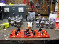
Time for some experiments. Thanks to George for pointers on different sweep tubes to try. A big sweep tube amp might be in the future, depending on the condition of those 6LR6's on the left.
Time for some experiments. Thanks to George for pointers on different sweep tubes to try. A big sweep tube amp might be in the future, depending on the condition of those 6LR6's on the left.
Attachments
Last edited:
I see some of the magic tubes in the picture. There aren't too many of them left, so I plan to get a few more before they are gone forever. My board seems happy running them in the 80 to 100 WPC range using a pair of the "ugly OPT's" wired for 3300 ohms.
The red board has been temporarilly voted off of the workbench so I can finish 3 different Simple P-P builds.
At least Sherri thought the board is "pretty". I have since uglied it up a bit.
The red board has been temporarilly voted off of the workbench so I can finish 3 different Simple P-P builds.
my wife is thrilled already (not).
At least Sherri thought the board is "pretty". I have since uglied it up a bit.
Last edited:
The red board has been temporarilly voted off of the workbench so I can finish 3 different Simple P-P builds.
That is the first time I have seen that much of the surface of my workbench in years. I finally finished the basement renovations a month or two ago, so the heap of tools and junk has finally been put/shoveled away. Can do some tube projects there again. I've been meaning to rig up the SSE and TSE for some measurements, but lacked the space to do so.
Also have one of Pete's sound card interfaces mostly-stuffed, but I am missing a few components. Will have to keep using the Vellemans for now. I need a real scope.
The red board will be voted off the bench for a while shortly as well....
At least Sherri thought the board is "pretty". I have since uglied it up a bit.
You are lucky. Amy just rolled her eyes at mine. 😉
Hi guys,
Just a couple of quick questions. I am almost finished wiring up my amp🙂.
1) While looking at the Edcor opt wiring diagram I noticed that it showed the white wire as common. This is the one I should be hooking up to the neg speaker post. The only reason I ask is because in petes pics he has the yellow hooked up there. Did Edcor maybe change things around?
2) Next question is I have set up posts for 4 and 8 ohm taps. Can I just hook up the unused 16 ohm lead for the feedback?
Thanks in advance for your help,
Al
1) It is normal to swap these for negative feedback to work.
2) You should use the tap that Pete is using.
2) You should use the tap that Pete is using.
Thanks for the reply. So I guess I will have to go under the amp to select 4 or 8 ohm set up, and not just have posts on top to switch quickly. What if I dont use feedback? Can I then simply hook up the common to neg and 4 ohm to one post and 8 ohm to another?
Thanks for helping out a newb,
Al
Thanks for helping out a newb,
Al
Sure you can. Ground the 16-ohm tap instead of the common tap. The 8-ohm tap becomes the 4-ohm tap and the 4-ohm tap becomes the 8-ohm tap. The common tap is now the 16-ohm tap.
Thanks, do I just hook up the feedback to both the 4 and 8 ohm posts both? Sorry for the stupid questions.
Al
Al
Just one more question. does anyone have a close up pic of the wiring of the eic socket, since the one in petes pics is different than the one in the bom?
- Home
- Amplifiers
- Tubes / Valves
- Posted new P-P power amp design