Pete: Would the Edcor 7.6k 25W 8-ohm transformer (CXPP25-8-7.6k) be 'close enough' (you specify 8k) for the circuit? It's about $10 cheaper and I don't want to incur the wrath of my wife. What impact would this have (if any)?
Thanks!
p.s. If you need hardware for a low-end server, I'm sure I have some I could give you gratis - I'm sure others do as well.
Thanks!
p.s. If you need hardware for a low-end server, I'm sure I have some I could give you gratis - I'm sure others do as well.
Pete: Would the Edcor 7.6k 25W 8-ohm transformer (CXPP25-8-7.6k) be 'close enough' (you specify 8k) for the circuit?
Yup, should work just fine.
Pete
Received Pete's bloody red board .... wow .... looks sexy! Might design an arcrylic enclosure to display it !?
BTW, how do you fit a Sylvannia 6JN6 with pin dia. of 3/4" into the mother board of 1" diameter?
Thanks!
BTW, how do you fit a Sylvannia 6JN6 with pin dia. of 3/4" into the mother board of 1" diameter?
Thanks!
BTW, how do you fit a Sylvannia 6JN6 with pin dia. of 3/4" into the mother board of 1" diameter?
You will need some compactron sockets, designed for PCB mounting.
Jeff
BTW, how do you fit a Sylvannia 6JN6 with pin dia. of 3/4" into the mother board of 1" diameter?
Thanks!
Pacific T.V. - Vacuum Tube Sockets - Compactron
Part # B12C-PCB - $4.00 / ea.
-D
Derek ... thanks for that link!
Zekk
Yup, should work just fine.
Pete
The bummer is Edcor is now taking 6+ weeks to ship...I won't get these until the end of February. 🙁
Ah well, that'll give me time to build the chassis and get everything else put together. Anticipation...
-D
Wow! On 1-5-10 I ordered two CXPP30-MS-5K and they quoted me 3-4 weeks. They must have gotten a bunch of orders.
I'm stuffed! Well, almost at least.
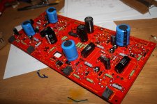
I'll be using a Hammond 370HX for power and not sure about the output transformers. I hope to fit it all on a 17x10 plate, but it's gonna be tight.
I decided to go with some 82uF 500v's (the big blue ones) and they crowd some of the parts. A couple items had to go on the other side of the board.
q1, and q2 will be FUJI 2SK3524's (600V, 8A).
Attachments

Last edited:
With regard to the MOSFET heatsinks, how small is too small? I was planning on using a pair of stamped metal TO-220 heatsinks that I had laying about like these:

Would I risk frying the MOSFETs or would these be sufficient?
-d
Would I risk frying the MOSFETs or would these be sufficient?
-d
They look too small to me, especially if they're enclosed in the case.
If I'm not attaching this to the top panel, any ideas on how large they do have to be?
-D
I think I may have a solution - I just ordered a couple of small (.5x.5x.75") copper blocks that will be sandwiched between the MOSFETs and the underside of the chassis. The copper will act as a heatsink to the MOSFETs and the aluminum chassis plate will be a heatsink to the copper...sort of similar to modern CPU heatsinks. I'll just use some thermal epoxy between the chassis and the blocks and tap the blocks for a screw from the MOSFETs.
Any potential problems with this plan that I'm missing?
-D
Any potential problems with this plan that I'm missing?
-D
I think I may have a solution - I just ordered a couple of small (.5x.5x.75") copper blocks that will be sandwiched between the MOSFETs and the underside of the chassis. The copper will act as a heatsink to the MOSFETs and the aluminum chassis plate will be a heatsink to the copper...sort of similar to modern CPU heatsinks. I'll just use some thermal epoxy between the chassis and the blocks and tap the blocks for a screw from the MOSFETs.
Any potential problems with this plan that I'm missing?
-D
Well, apart from copper being expensive (I would think in this situation aluminium would be fine) I think it should transfer the heat to the top plate fine, but you're going to end up with a pretty hot top plate. Shouldn't matter too much as long as it pulls enough heat from the FETs, unless you have a painted top plate, where it might cause problems with cracking or peeling.
Well, apart from copper being expensive (I would think in this situation aluminium would be fine) I think it should transfer the heat to the top plate fine, but you're going to end up with a pretty hot top plate. Shouldn't matter too much as long as it pulls enough heat from the FETs, unless you have a painted top plate, where it might cause problems with cracking or peeling.
The top plate is black anodized aluminum so cracking/peeling shouldn't be a problem. The nice thing is that I'm paying about $6 (sans shipping & tax) for four pieces (two 0.5x0.5x0.5 and two 0.5x0.5x0.75 inch) of copper, so not too expensive. 🙂
I'm actually paying more ($12!!!) for the thermal adhesive than the copper.
-D
Hi,
I just bought the PCB. I am sourcing other parts. This would be my first tube amp. I have modified a used preamp, changing SRPP to mu-follower.
I have a pair of OPT with 10K source impedance. Does it suit this amp?
I also have a pair of R-core transformer, 110-0-110 pri and 2x9V secondary, 50W. That would be about 2K5:8. If I use 2K5 source impedance, what anode voltage should I use?
The top plate is black anodized aluminum so cracking/peeling shouldn't be a problem. The nice thing is that I'm paying about $6 (sans shipping & tax) for four pieces (two 0.5x0.5x0.5 and two 0.5x0.5x0.75 inch) of copper, so not too expensive. 🙂
I'm actually paying more ($12!!!) for the thermal adhesive than the copper.
-D
The 0.5 x 0.5 x 0.75 inch copper blocks are a perfect fit. Drilled out a hole in each for self-tapping screws to attach the MOSFETs and then used Arctic Silver thermal epoxy to adhere the blocks to the underside of the top plate. For anyone building this amp who doesn't want to mess around with extending the MOSFET leads, I highly recommend this method of heat-sinking the MOSFETs...at least in theory - still need to fire this sucker up and see what happens when the rubber hits the road.
Now if only Edcor would ship my OPTs then I could fire this up and start testing it (and listening to it once everything is DMM-ed out). Of course I still have to build the chassis to hold the plate...<grumble>
Patience is not my forte.

-D
My "red board" has been sitting cold and lonely on top of my computer since early November. No electrons have flowed through it. I have been too busy, and several Simple P-P builds have my bench top filled. During this time I have collected a big bunch of tubes to try.
Unlike most of my high school friends whose first jobs were flipping burgers or pumping gas (it was 1968), my first job was fixing TV sets (age 16). I remembered some of the monster sweep tubes that I couldn't blow up. There were 6DQ5's, 6CB5's and the biggie, the 6KD6's. I didn't get to play with many because I couldn't find any "bad" ones that actually worked. They didn't die too often unless something was really wrong. In my recent past (last 15 years) I have revisited most of the tubes that I met in the 60's and 70's but I have never collected enough 6KD6's to play with, until now.
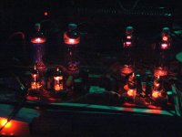
Another forum member sent me some tubes in unknown condition to evaluate. I promised to test them and send him a suitable trade if there were any useful tubes. There were four 6KD6's. I have 3 6KD6's. I have a big red board. Last night I packed up the dual Simple P-P amp and carted it all off to wood shop class to build a cabinet, so I have an empty spot on the bench. Do tubes glow?
I connected the red board back up with the 6HF5's still in it. This time I got out the big Plitron OPT's that I have. These are rated for "400 watts at 20 Hz" and have a 1250 ohm impedance. I have already found that they work OK at 2500 ohms and 5000 ohms by hooking the 8 ohm load to the 4 ohm or 2 ohm tap. The 6HF5's really didn't like the 2500 ohm load but did manage 130 watts with 525 volts of B+ and a faint hint of redness. They previously made 125 watts with a 3300 ohm load.
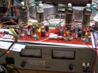
I stuck a pair of 6KD6's in the board, set the power supply on 450 volts and cranked. Two NOS tubes (One GE, one RCA) in the right channel, but the bias won't equalize. Something is wrong. I decided not to risk NOS tubes, so I stuck in the crustiest looking pair of tubes that I had. A pair of Admiral branded GE's. These tuned right up to Petes prescribed 40 mA each. Nothing exploded, so i turned up the power supply I ran this amp for half an hour at ridiculous power levels. I swapped tubes around until I have found 4 tubes that play nice with each other.
I shut off the fun before I blew anything up. Tomorrow I should have more time to experiment.
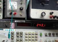
Note the meters on the plate supply. 550Volts at 1.1 AMPS! The watts are displayed on the 8903A. In the ususal night photo, there was nothing glowing. Yes the audio analyzer shows 243 watts. That is just one channel.
Unlike most of my high school friends whose first jobs were flipping burgers or pumping gas (it was 1968), my first job was fixing TV sets (age 16). I remembered some of the monster sweep tubes that I couldn't blow up. There were 6DQ5's, 6CB5's and the biggie, the 6KD6's. I didn't get to play with many because I couldn't find any "bad" ones that actually worked. They didn't die too often unless something was really wrong. In my recent past (last 15 years) I have revisited most of the tubes that I met in the 60's and 70's but I have never collected enough 6KD6's to play with, until now.
Another forum member sent me some tubes in unknown condition to evaluate. I promised to test them and send him a suitable trade if there were any useful tubes. There were four 6KD6's. I have 3 6KD6's. I have a big red board. Last night I packed up the dual Simple P-P amp and carted it all off to wood shop class to build a cabinet, so I have an empty spot on the bench. Do tubes glow?
I connected the red board back up with the 6HF5's still in it. This time I got out the big Plitron OPT's that I have. These are rated for "400 watts at 20 Hz" and have a 1250 ohm impedance. I have already found that they work OK at 2500 ohms and 5000 ohms by hooking the 8 ohm load to the 4 ohm or 2 ohm tap. The 6HF5's really didn't like the 2500 ohm load but did manage 130 watts with 525 volts of B+ and a faint hint of redness. They previously made 125 watts with a 3300 ohm load.
I stuck a pair of 6KD6's in the board, set the power supply on 450 volts and cranked. Two NOS tubes (One GE, one RCA) in the right channel, but the bias won't equalize. Something is wrong. I decided not to risk NOS tubes, so I stuck in the crustiest looking pair of tubes that I had. A pair of Admiral branded GE's. These tuned right up to Petes prescribed 40 mA each. Nothing exploded, so i turned up the power supply I ran this amp for half an hour at ridiculous power levels. I swapped tubes around until I have found 4 tubes that play nice with each other.
I shut off the fun before I blew anything up. Tomorrow I should have more time to experiment.
Note the meters on the plate supply. 550Volts at 1.1 AMPS! The watts are displayed on the 8903A. In the ususal night photo, there was nothing glowing. Yes the audio analyzer shows 243 watts. That is just one channel.
Attachments
Last edited:
Ah! 6KD6's! I had a ham friend when I was in my teens, who had a Yaesu FT-400 (I think it was) with two of those as finals. We used to have fun seeing how much we could push out the antenna with those. We soon found any suspicious coaxial connections, they were the ones that had flames coming out of them 🙂
Those tubes just seem to keep coming back for more. Wish I had some to play with now.
Those tubes just seem to keep coming back for more. Wish I had some to play with now.
- Home
- Amplifiers
- Tubes / Valves
- Posted new P-P power amp design