Volume Control using Muses72323+ArduinoNano

@meanman1964
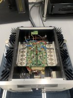
Absolutely gorgeous job. I like how the entire amplifier is enclosed. This is a great consideration especially with Class AB designs where idle current/bias is low. Very nice and clean. And dual mono to boot!
It looks like a Modushop 4U/300 enclosure but steel based, correct?
Best,
Anand.
Absolutely gorgeous job. I like how the entire amplifier is enclosed. This is a great consideration especially with Class AB designs where idle current/bias is low. Very nice and clean. And dual mono to boot!
It looks like a Modushop 4U/300 enclosure but steel based, correct?
Best,
Anand.
I switched to metal screws for the TO3Ps which was a good idea anyway, but it did not fix the problem. In the end I switched to mica + grease on one of the boards and did a (very scientific) test where I ran the amp hard and held my thumb on a TO3P of each board (mica + grease versus silpad) and the difference was astonishing. The mica + grease combo does a much, much better job of conducting the heat into the big sinks. What I can say is do not bother with TO3P silpads from Jaycar (this will only be relevant to AU/NZ). The issue is that Jaycar don't sell TO3P mica pads so I had to harvest mine from the parts bin.Maybe it's not a good idea to use nylon screws? Won't they stretch and deform slightly with temperature? The pressure on the transistor needs to be consistent otherwise you'll get small pockets under the transistor that aren't in contact with the pads. Thermal paste should improve things.
It was my first time using mica + grease and it is very messy and fiddly but the end result was worth the effort.
Patrick,
A beautiful job! Very nice wiring - did you resolve the hum?
Hugh
A beautiful job! Very nice wiring - did you resolve the hum?
Hugh
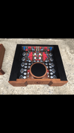
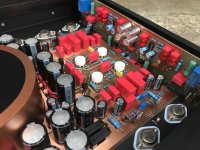
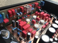
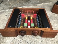
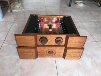
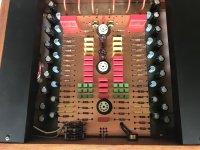
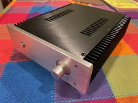
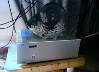
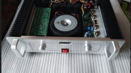
is another version of counterpoint
that uses a transistor as the final amplifier that arranges a quasi complementary circuit instead of the original output that is a MOSFET
The resulting sound is soft and smooth. different from the original one that uses mosfet
Compatible with preamp clone mcintosh c22
sound matching all frequency bands come out completely in
Attachments
-
 2F381A4D-E155-480F-84CC-9E6877F3A28F.jpeg626.7 KB · Views: 720
 -
 74BBD14D-B52F-467F-A4FD-B996E2070412.png261.1 KB · Views: 690
 -
 52C73556-2D1C-4DF2-8D1C-DBA91615AB42.jpeg476.4 KB · Views: 640
 -
 B6542636-4730-47B8-8C06-858EC6DA8544.jpeg435.7 KB · Views: 658
 -
 1C5A853C-3032-4120-9CE3-1C70AD0111BC.jpeg597 KB · Views: 658
 -
 DB5F82EA-A375-4613-B63A-62DD59CC9E97.jpeg370.2 KB · Views: 635
 -
 53A4FC51-C098-4E64-97FB-FE44834E5D75.jpeg290.2 KB · Views: 637
 -
 5A1D6D3F-F08D-4496-BBFE-EDA2D15F6BD2.jpeg446 KB · Views: 710

Been back to working my NIC opamp VAS design (actually replacing a damaged PCB that had a heatsink dropped on it...), so I thought I post a couple of images while at it. The original thread is: https://www.diyaudio.com/community/threads/nic-opamp-vas-topology.348646/
The main PCB (all but output stage):

The output stage PCB:

The output devices are ECX10P20 / ECX10N20 lateral FETs, so no thermal feedback needed for the bias, a tiny 11 turn cermet preset to set the bias.
The Eagle schematic for the main PCB:

The main PCB (all but output stage):
The output stage PCB:
The output devices are ECX10P20 / ECX10N20 lateral FETs, so no thermal feedback needed for the bias, a tiny 11 turn cermet preset to set the bias.
The Eagle schematic for the main PCB:
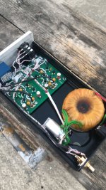
So here’s my first DIY amp project. It’s not a full DYI, more of just a recase with some add ons but they sound amazing, have TONs for power and they now look as good as my Carver Amazings now. The original amps are AB International 600As. They are bridged so each case is now a mono block weighing in at about 65lbs each and puts out over 1100 watts at 4 ohms. I cut the output boards in half so I could mount each half on each side. Had to modified the meters to work with a normal driver board. Also added a 25 amp solid state relay that’s trigged from my preamp. Next step, get rid of the clip circuit on the input side and build a new circuit the monitor the actual output.
Attachments


any more info is this documented anywhere ?View attachment 1072930
6-channel class-B(AB) amplifier with Linkwitz-Riley crossover and protection circuit on MOSFET relays.
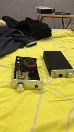
My little Breeze Audio class A power amp. I used to use active crossovers, but switched to a simple amplifier highpass filter, to the point just above where a pair of full range drivers flap around without producing much sound, and augment the lower range with an open baffle bass frame.
Maybe a little cleaner than without highpassing the amp; especially in the upper midrange.
Maybe a little cleaner than without highpassing the amp; especially in the upper midrange.
Attachments

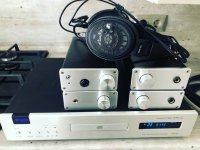
Another day, another Class AB amp. This time, the Neurochrome Modulus 686:


More info and preliminary measurements here.
Best,
Anand.
More info and preliminary measurements here.
Best,
Anand.
nice looking
but these heatspreaders are flimsy
not enough contact area, not thick enough, not stiff enough
with heatspreaders, there is really no overkill - you need to overcome additional heat transfer step, sorta go in territory of one step back and two steps forward
but these heatspreaders are flimsy
not enough contact area, not thick enough, not stiff enough
with heatspreaders, there is really no overkill - you need to overcome additional heat transfer step, sorta go in territory of one step back and two steps forward
DB1 ( BJT/MOSFET )
Simple, yet brutal and extraordinary 🙂


Simple, yet brutal and extraordinary 🙂
Nice clean layout.
Vertical FET "quasi amp". Might of been advantageous to add beta enhancement to Q7. More OLG = less THD.
Vertical FET "quasi amp". Might of been advantageous to add beta enhancement to Q7. More OLG = less THD.
- Home
- Amplifiers
- Solid State
- Post your Solid State pics here