Home brew mosfet power amplifier
Here are three photo's of a mosfet power amplifier I built a few years ago.
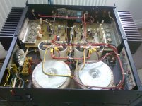
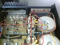
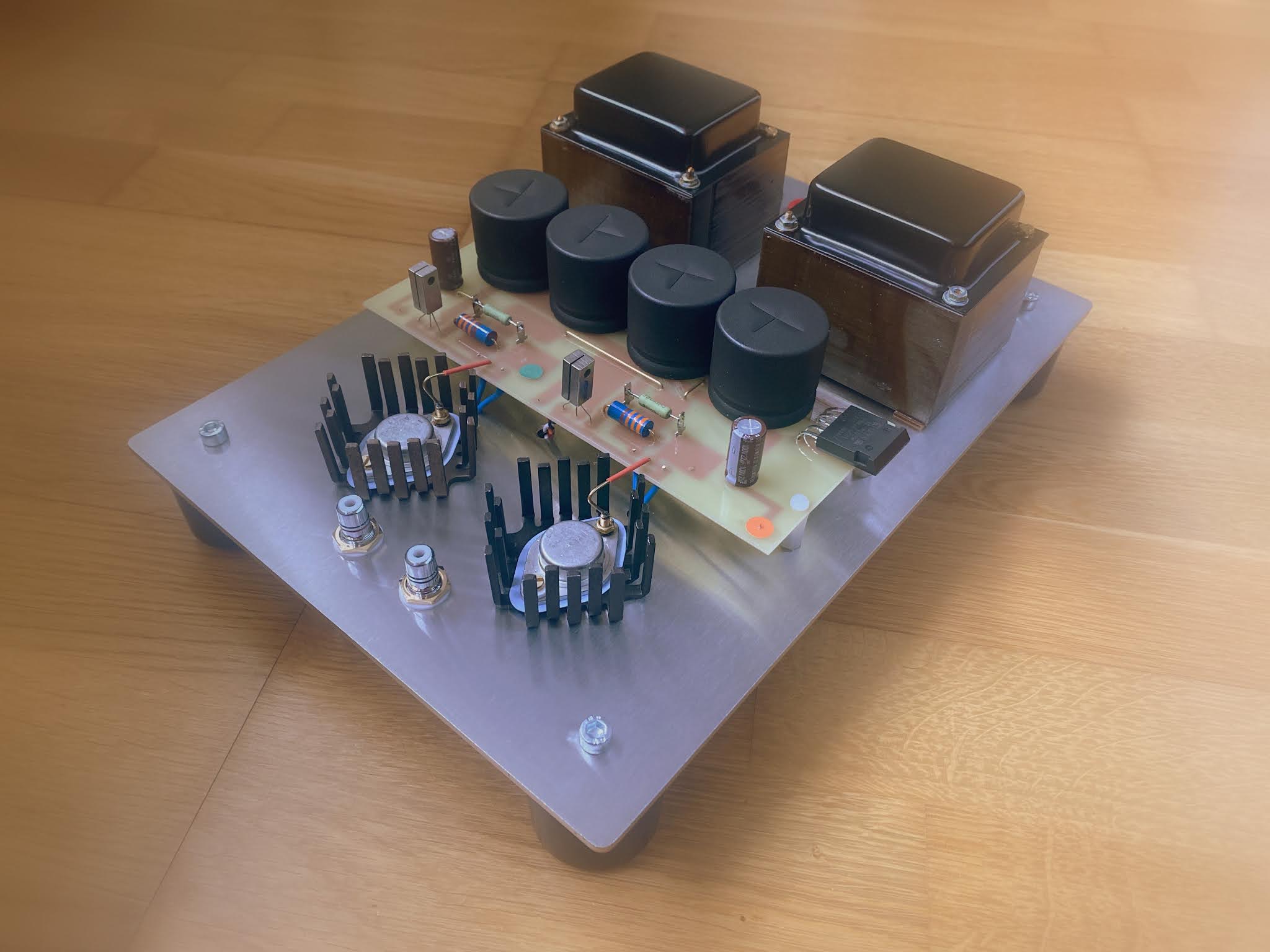
The amplifier is of dual monaural design with each channel having it's own power supply. The toroidal mains transformers are 625VA. I incorporated dc offset loudspeaker protection and a power output monitor. Continuous sinusoidal output power is 270W per channel into 8 ohms. The power mosfets are Exicon laterals and the supply rails are +80-0-80v.
Here are three photo's of a mosfet power amplifier I built a few years ago.
The amplifier is of dual monaural design with each channel having it's own power supply. The toroidal mains transformers are 625VA. I incorporated dc offset loudspeaker protection and a power output monitor. Continuous sinusoidal output power is 270W per channel into 8 ohms. The power mosfets are Exicon laterals and the supply rails are +80-0-80v.
Attachments
Nice 🙂
The transistor count suggests maybe the original Hitachi application note style of topology... which was excellent.
Are those RIFA caps on the mains input panel ? If so then it might be worth a swapsie with some modern Class X parts. The RIFA's can and often do go up in smoke.
The transistor count suggests maybe the original Hitachi application note style of topology... which was excellent.
Are those RIFA caps on the mains input panel ? If so then it might be worth a swapsie with some modern Class X parts. The RIFA's can and often do go up in smoke.
The caps on the mains input filter panel are class x.
I remember I salvaged the mains filter from a scrap Farnell SMPS.
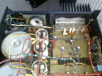
The driver circuit is based upon the old Maplin 1KW mosfet power amp design. However, I have changed components to improve deep bass response and lower the gain of the amplifier to 22.
After many years of reliable service I recently had a problem with the left channel. Although the sound quality was fine I noticed that the heat sink was cooler than the the heat sink on the right channel.
After investigation I found one of the ECF10N20 n-channel mosfets had failed and wasn't conducting at all. I removed the mosfet and found it showed 160 ohms resistance between gate and source. I have absolutely no idea why the mosfet failed.
I remember I salvaged the mains filter from a scrap Farnell SMPS.
The driver circuit is based upon the old Maplin 1KW mosfet power amp design. However, I have changed components to improve deep bass response and lower the gain of the amplifier to 22.
After many years of reliable service I recently had a problem with the left channel. Although the sound quality was fine I noticed that the heat sink was cooler than the the heat sink on the right channel.
After investigation I found one of the ECF10N20 n-channel mosfets had failed and wasn't conducting at all. I removed the mosfet and found it showed 160 ohms resistance between gate and source. I have absolutely no idea why the mosfet failed.
That sounds an unusual failure, particularly on an amp that has been in use for ages. It kind of rules out static damage and so on. Very strange.
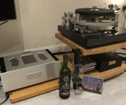
It’s Yo-yo Ma & Kathryn Stott’s ‘La Belle Epoque’, Rioja and the kx-Amp through the KEF LS50’s tonight.
Attachments
Last edited:
I apologize for my poor attempt at humor.
Your amp and turntable look fantastic and I’m sure sound exquisite. Music appreciation is always good with a fine Rioja!
Your amp and turntable look fantastic and I’m sure sound exquisite. Music appreciation is always good with a fine Rioja!
Looks like a rendering image
Hi,
new"rendering image" 😀😀😀
Regards
Rock
That sounds an unusual failure, particularly on an amp that has been in use for ages. It kind of rules out static damage and so on. Very strange.
Hi Mooly and thanks for your reply.
Inspecting the mosfet that had failed I notice that it has a dark area on it's cap which I cannot remove using alcohol. Seems like the metal has changed colour due to over heating.
When I removed the faulty mosfet I noticed that the nuts and bolts that hold it down to the heat sink bracket weren't as tight as they should be.
I think that's because the lock washers under the nuts have compressed over the years.
Also the nuts holding down the other three mosfets needed tightening.
After replacing the failed mosfet I checked the voltages across each source ballast resistor and found the mosfets weren't sharing the quiescent current very equally. Normally each mosfet should pass about 100mA quiescent current but I found one passing 45mA and another passing 64mA. On the other channel all the mosfets pass the same current plus or minus a few mA.
I have therefore decided to replace all the mosfets on the left channel which will hopefully restore quiescent current balance. I thought that lateral power mosfets were immune to overheating. I've ordered the mosfets from Profusion and I will install them at the end of next week. I will report back my findings.
The picture of his amp and phono also had a bottle of wine, assume he was drinking it while listening to the music on his new amp??!!
There is no bottle of wine in the picture. I've never had any wine in my listening room. Also I don't like or drink wine.
Please highlight the area in the picture where you see a bottle of wine.
Please highlight the area in the picture where you see a bottle of wine.
- Home
- Amplifiers
- Solid State
- Post your Solid State pics here