By the way, I'm thinking about using other output transistors , I have from another project 2sc2608 2sa1117 to3 sanken nos ,the entire output board will be mounted in a u profile aluminium, the to3 drilled in thorough sides of profile, think it will give good heat dissipation.
If you have pics, suggestions, or other input I'm in 🙂
If you have pics, suggestions, or other input I'm in 🙂
Yes I 'm going to build a complete amp. I got the same set of pcbs as you. I think you should be ok with the 2sa1117/2sc2608 pairs. They have relatively low hfe and the ft isn't even quoted, so I assume that its quite low. This can be important with output stages like the Bryston as its almost impossible to get it stable if you use high hfe, high gain modern transistors. That's also why the output stage has gain; its not unity gain stable. I don't intend to experiment with the output stage but to try some of Douglas Self or Bob Cordell's improvements to the input stage. Maybe we should start a separate thread rather than hijack this one.
Hmm, just found more complete datasheets for the 2sa1117/2sc2608 pair and the ft is given as 20MHz as opposed to 4MHz minimum for the mjl21193/94. 20MHz may be a bit high for ft, but if you try the amp with single output pairs and a current limited power supply, as suggested in the debugging instructions that came with the pcbs, then you should be safe enough if the amp oscillates. Keep an eye on R59 ( 10R 3W ) which will get hot very rapidly if the amp oscillates.
Greg Ball Mono's
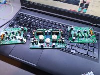
After almost giving up on this project following frying one of the boards, I finally got them working and finished. Here's my pair of GB150D Mono Blocks in the making....


After almost giving up on this project following frying one of the boards, I finally got them working and finished. Here's my pair of GB150D Mono Blocks in the making....
Thanks guys, they sound superb too. I had a McIntosh 2600, which got rapidly dumped after about 10 minutes of listening to these..

Hi chalky, are you making progress on your boards?,starting a new Bryston clone thread might be an idea, but I'm not online that often so I would not be able to participate often, don't now if anybody else are fiddling with Therese boards.Hmm, just found more complete datasheets for the 2sa1117/2sc2608 pair and the ft is given as 20MHz as opposed to 4MHz minimum for the mjl21193/94. 20MHz may be a bit high for ft, but if you try the amp with single output pairs and a current limited power supply, as suggested in the debugging instructions that came with the pcbs, then you should be safe enough if the amp oscillates. Keep an eye on R59 ( 10R 3W ) which will get hot very rapidly if the amp oscillates.
I'm having difficulty finding the two bridge rectifiers, they're leg orientation isn't all that standard, also the two spdt switches on input board are troubling me, so now I'm stuck with 35 CK switches and none fit, the guy only sold as lot..🙂
I would love some pics of your progress and info on any enhancements on the input board.
Regards thomas
Hi Thomas, My board sets have arrived and I'll be picking them up from the Post Office tomorrow ( need to pay some import duty ). I have bought complete semiconductor sets for the four channels that I'll be building. Easy to get almost perfect matches between groups of npn or pnp transistors, but alas npn to pnp matching between any of the complementary pairs used isn't that great. Doesn't matter quite so much for the output stages because of the topology, but would have reduced the raw thd of the input stages a little if matching was better. Ah well thank goodness for nfb! Regards, David
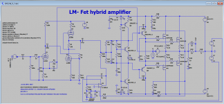
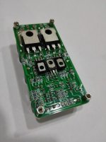
My miniature Doug Self style "Blameless" amp, note the AA cell for scale. Mostly SMT,
ignore the part numbers in the schematic, the small signal transistors are BC850C and BC860C, with FMMT624 and FMMT723 higher voltage devices for the cascode stages.
Drivers MJE15030/MJE15031, Output transistors NJW1302G and NJW3281G.
Yes, I know the bias pot isn't in the right place in the circuit (it fails open the amp
self-destructs!) Note there are two alternate footprints for the bias transistor, not two actual transistors!


I tried to arrange the ground and power planes to be only under the transistors whose signals were referenced to that rail. Note my use of kapton tape as a thermal pad - not sure this is a brilliant idea but I wanted to test it and didn't have the right pads!
ignore the part numbers in the schematic, the small signal transistors are BC850C and BC860C, with FMMT624 and FMMT723 higher voltage devices for the cascode stages.
Drivers MJE15030/MJE15031, Output transistors NJW1302G and NJW3281G.
Yes, I know the bias pot isn't in the right place in the circuit (it fails open the amp
self-destructs!) Note there are two alternate footprints for the bias transistor, not two actual transistors!
I tried to arrange the ground and power planes to be only under the transistors whose signals were referenced to that rail. Note my use of kapton tape as a thermal pad - not sure this is a brilliant idea but I wanted to test it and didn't have the right pads!
Last edited:
Dont you find the outputs way too slow for such an otherwise nice circuit ?
As I said in the text, ignore the part numbers in the schematic - the outputs are
NJW1302G/NJW3281G - its slow enough doing stuff in Eagle to have to define 8 new devices wasn't going to happen that day!
Basically I have very little of the free time, but there is always a few minutes every day for a new crazy project.
Nice Borys,interesting!🙂
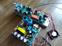
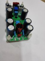
My amplifier board OM2.7.Сhecked together with protection and SMPS SG3525.
Amp Class AB.
Power 100W/4Ohm. +-35V
100W/8Ohm +-45V
Distortions 10W/5Ohm about 0.0005 %.
circuit boards can be made Усилитель Оnly musik 2.7 - Share Project - PCBWay
you can read about the amplifier Усилитель мощности Only Music 2.7 (ex "оплеуха микрухам") [2018]
Amp Class AB.
Power 100W/4Ohm. +-35V
100W/8Ohm +-45V
Distortions 10W/5Ohm about 0.0005 %.
circuit boards can be made Усилитель Оnly musik 2.7 - Share Project - PCBWay
you can read about the amplifier Усилитель мощности Only Music 2.7 (ex "оплеуха микрухам") [2018]
Attachments
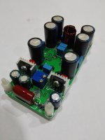
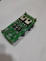
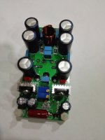

Nice, very compact - is that a 4-layer pcb? I note its different from on your site.My amplifier board OM2.7.Сhecked together with protection and SMPS SG3525.
Amp Class AB.
Power 100W/4Ohm. +-35V
100W/8Ohm +-45V
Distortions 10W/5Ohm about 0.0005 %.
Nice, very compact - is that a 4-layer pcb? I note its different from on your site.
This is a 2 layer PCB.This is a fee for the link. There are photos
- Home
- Amplifiers
- Solid State
- Post your Solid State pics here